6
V1.1
2.
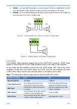
MONO – Use two 50W 4R speakers, one each across the L+/L- and R+/R- for the left
and right speakers. Both speakers output the same audio signal in this mode.
3.
BRIDGE – Use one 100W 2R speaker between the R- and L+ terminals only. The R+ and
L- terminals are not used in Bridge mode.
Figure 7 - Wiring Details for Stereo or Mono Configuration
Figure 8 - Wiring Details for Bridge Configuration
Loop Out
The amplifier output signal is always sent to the LOOP OUT connector. LOOP mode
allows for more than one SY-2A-100W amplifier to link to the LINE of next amplifier.
In this mode the first amplifier should have its LOOP switch OFF and all the other
amplifiers should have the LOOP switch set to ON. Only the first amplifier will have
control of the output volume level and also allows a microphone to be used.
Note:
The following conditions apply when using the LOOP OUT switch:
LOOP OUT Setting
OFF
ON
Operating Mode
NORMAL
LOCKED
Front Panel Control
All controls will function as
described in the next section
The front panel controls are
locked and cannot be used.
LINE Input
Either LIN or OPT as previously
selected
Only the analogue line (LIN)
input is selected
LINE Volume
As previously set by the volume
control or Line mute button
Fixed at 100%
MIC Volume
As previously set by the volume
control or Mic mute button
Automatically muted
Содержание 2A-100W
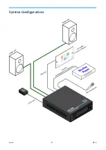
Страница 8: ...sy uk 8 V1 1 System Configuration ...
Страница 11: ...V1 1 11 sy uk NOTES ...
Страница 12: ...sy uk 12 V1 1 NOTES ...


