

_____________________________________________________________________________________
SWS
–
7695 Blackburn Parkway, Niagara Falls, ON Canada
Tel: 1-877-357-0222 | Fax: 905-357-9122 | [email protected]
300138 Rev. 8
Page
2
of
7
Mounting
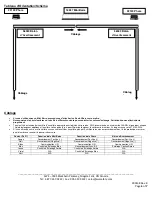
Minibar (#16397) Permanent Mount
Select a surface where the light is visible and free of obstruction. Mounting brackets are available from the
manufacturer if required.
A straight level is highly recommended to ensure the light is level on two axes.
Ensure the vehicle is on level ground when installing.
Outer dome does not require removal for installation.
Take note of the “Pattern Starts Here” label.
It must face the front of the vehicle.
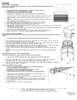
1. If you are not using an SWS mounting bracket, use the images on the right as a guide
. Drill a ½” wire
hole (check bottom of minibar to confirm where the wires exit the product) and four
5
/
16
” holes as
shown.
2.
Take the four ¼”
-20 bolts and insert them into the T-slots on the bottom of the base of the light. Look
for the milled holes to insert the bolt heads.
3. Slide one bolt to each corner of the base approximately 1.5 - 2 inches in from the edge.
4. Place the large rubber grommet into the hole drilled in the mounting surface for wires.
5. Place the 4 rubber standoffs on each bolt from the underside of the light.
6.
If your light has an external connector,
connect the wiring pigtail to the connector prior to the next step. A small amount
of dielectric grease is recommended.
7. Pass the bolts through the mounting surface keeping the rubber standoffs between the light and the mounting surface. Be
sure to pass the wires through their grommet.
8. From the underside of the mounting surface, place a flat washer and self-locking nut onto each bolt.
9. Tighten the nuts with a
7
/
16
” wrench while using a straight level to ensure the light is level.
Beacon (#22120) Permanent Flange Mount
Select a surface where the light is visible and free of obstruction. Mounting brackets are available from the manufacturer if
required.
Take note of the “Pattern Starts Here” label. They both must face the front of the vehicle.
1. Select a mounting area that will allow the light to function unobstructed. Be sure that the light is mounted vertically, as
any other orientation will decrease the effectiveness of the light.
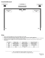
2. If you are not using an SWS mounting bracket, you will have to drill three (3) holes into the surface using a
7
/
32
” drill bit.
Use the foam pad as a template. Be sure to drill a hole in the center for the wires.
3. Set the foam pad down on the surface and align the holes with the pre-drilled mounting holes. Set the light onto the pad
aligning the flange holes with the holes on the pad, passing the wires through the center hole.
4. Pass the #10 Hex Drive Machine screws through the three flange mounting locations, the pad, and the mounting
surface.
5. Install the #10 Flat washers and #10 self-locking nuts. Tighten the screws and self-locking nuts, but
do not over
tighten.
Beacon (#22120) Permanent ½” NPT Conduit/Pipe Mount
The included flange does not need to be present and can be removed if desired.
Take note of the
“Pattern Starts Here” label. They both must face the front of the vehicle.
1. Thread wires through pipe/conduit. This may have to be done after wiring to ensure proper length of the wires.
2. Thread light no more than
3
/
8
” onto the pipe/conduit using the center ½” NPT hole in the base.
3. Secure the light tightly to ensure proper connection to the pipe/conduit.
Be careful not to over-tighten
. Thread tape or
a locking nut can be used but is not supplied.
Warning Stick (#56043) Permanent Mount
Select a surface where the light is visible and free of obstruction. Mounting
brackets are available from the manufacturer.
A straight level is highly recommended to ensure the light is level.
Ensure the vehicle is on level ground when installing.
Vertical sticks should have the wires to the bottom of the mounting orientation.
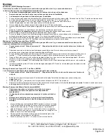
1. If you are not using SWS mounting brackets, you must drill
5
/
16
” diameter holes in the
mounting surface. A minimum of two are required.
2.
Slide the head of the ¼”
-20 bolt into one of the T-slots in the body of the light. The T-slots
can be accessed through the endcap.
3. Place a nylon spacer onto each bolt, then pass the bolt through the mounting surface.
4. From the opposite side of the mounting surface, place the flat washers and self-locking
nuts onto the bolts.
5. Tighten the nuts with a
7
/
16
” wrench or ratchet and socket.


