


7
20180620 Swegon reserves the right to alter specifications.
WISE
Damper
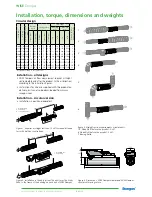
Changing the running direction
of the spring return actuator
Figure 28.
1. Standard installation of the spindle clamp.
2. Dismantle the circlip and spindle clamp.
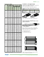
Replacing the spring return
actuator - Rectangular damper
Figure 20. Dismantling the spring return actuator.
1. Disconnect the cable.
2. Loosen the nuts on the spindle clamp (nuts 8 mm).
3. Dismantle 2 screws for the locking strip (screws TX20).
4. Lift off the motor.
Figure 22. For damper position “Normally open”
the damper should be open during installation
of the spring return actuator. The spindle clamp
then sits as shown above. NOTE! The spindle
clamp needs to be moved to the rear of the
motor, see figure 28-30.
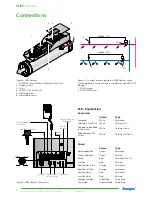
Replacing the spring return
actuator - Circular damper
Figure 25. Damper blade position “Normally
closed”.
Figure 23. Install the new spring return actuator.
1. Fit the motor on the damper spindle.
2. Fit the locking strip.
3. Make sure that the spindle clamp on the
motor is fitted according to one of the
designs shown in figure 21 or 22.
4. Tighten the nuts on the spindle clamp.
5. Connect the cable.
Figure 21. For damper position “Normally
closed” the damper should be closed during
installation of the spring return actuator. The
spindle clamp then sits as shown above.
Figure 24. Dismantling the spring return actua-
tor.
1. Disconnect the cable.
2. Loosen the nuts on the spindle clamp (nuts 8 mm).
3. Dismantle 2 screws for the locking strip
(screws TX 20).
4. Lift off the motor and spindle adapter.
Figure 26. Damper blade position “Normally
open”.
Figure 27. Install the new spring return actuator.
1. Fit the motor and spindle adapter on the
damper spindle.
2. Fit the locking strip.
3. Makes sure that the position of the damper
blade is correct, see figure 25 or 26. NOTE!
The spindle clamp is always fitted in the
direction as set out above on the circular
damper.
4. Tighten the nuts on the spindle clamp.
5. Connect the cable.
Figure 30.
1. Fit the spindle clamp and circlip as shown above.
2. Mounted with the spindle clamp.
NOTE! The signal must be inverted in software.
Figure 29. Reverse the motor.
1
2
3
4
1
2
3
4
1
2
1
2
Move to the right
Move to the left


