


GB.TBLZ275.160517
We reserve the right to alter specifications.
www.swegon.com 3
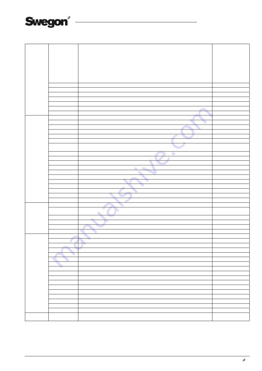
Setup
Control
Selection of control signal
Control = Modbus
DV is controlled from the hand-held micro terminal.
External signals are ignored, including:
Start/Stop signal (ON/OFF), and external control signal on wiring terminals (0 - 10 V in).
Control = 0-10 V DC
DV is controlled from external control signals, including:
Start/Stop signal (ON/OFF),
The fire mode signal (Firemode) as well as the external control signal (0 – 10 V in).
External stop and stop from the hand-held micro terminal have higher priority than start from the hand-held
micro terminal.
Modbus / 0-10 V DC
Rotation
Sets the current direction of rotation
Counter-clockwise
Min. rpm
Setting of the lowest speed of rotation (See also Section 10).
PM: 0 - ?* rpm
Max. rpm
Setting of the highest speed of rotation (See also Section 10).
PM: 0 - ?* rpm
Up Ramp
Setting of the ramp up time (See also Section 9).
0 - ?* s
Down Ramp
Setting of the ramp down time (See also Section 9).
0 - ?* s
Switch Hz
Setting of the switching frequency on the output.
Auto, Low, High
Exit
Return to the Main menu.
Alarms
Reset Alarm
Is activated in order to reset alarms when the maximum number of restarts has been exceeded.
Alarm stop
Shown when the motor has stopped due to an alarm.
Voltage low
Shown when an alarm has been initiated due to excessively low line voltage.
Voltage high
Shown when an alarm has been initiated due to excessively high line voltage.
Phase error
Shown when an alarm has been initiated because one line voltage supply phase is missing.
Current high
Shown when an alarm has been initiated due to excessively high output current.
Current limiting
Shown when an alarm has been initiated because the current limiting function is active (e.g. if the ramp
time is excessively short or if the motor is overloaded).
V ripple
Shown when an alarm has been initiated due to unstable line voltage.
Temperature high
Shown when an alarm has been initiated due to excessively high temperature in the frequency inverter.
Rotor Blocked
Shown when the rotor is blocked.
Rotation direction
Shown if the direction of rotation is wrong.
Internal com. error
Shown in the event of an internal communication error.
Internal HW fault
Shown in the event of a fault in internal hardware.
EEPROM error
Shown in the event of a fault in the internal memory (EEPROM)
Motor phase error
Shown in the event of a phase error on motor side (U, V, W)
Brake chopper fault
Shown in the event of a fault in the brake chopper.
Ext. 24V overload
Shown if the external 24 V input is overloaded.
Exit
Return to the Main menu.
Modbus
Address
Setting of the Modbus address display.
Baudrate
Setting of the baudrate display.
9 600,19 200, 38 400,
115 200 Bps.
Parity
Setting of the parity display.
None/Odd/Even
Stop bits
Setting and display of stopbits.
1/2
Time out
Time out, communication
0 - 200 sec.
Exit
Return to the Main menu.
About DV
Modbus addr
Status of the DV control system's Modbus address.
Drives type
Status of the type of DV control system.
1000- ?*
MOC SW ver.
Status of the DV control system's MOC program version.
MOC Boot ver
Status of the DV control system's MOC boot program version.
AOC SW ver.
Status of the DV control system's AOC program version.
AOC Boot ver
Status of the DV control system's AOC boot program version.
I/O SW ver.
Status of the I/O module's program version.
HW Cfg var
Status of the hardware configuration variant
HW Cfg var
Status of the hardware configuration version
Motor Cfg var
Status of the motor configuration variant
Motor Cfg ver
Status of the motor configuration version
Fan Cfg var
Status of the fan configuration variant
Fan Cfg ver
Status of the fan configuration version
User Cfg var
Status of the user's data variant
User Cfg ver
Status of the user's data version
Hterm SW ver.
Status of the hand-held micro terminal's program version
Exit
Return to the Main menu.
Config
Drive configuration
Enter PIN code for access.
Contact Swegon
*= Depends on size of the connected control system