7
W5
Smart
All rights to changes reserved.
2020-11-19
the adjustment feet, so that the unit tilts backwards by
a few degrees.
2.1.2 Ceiling mounting
The ventilation unit can also be mounted in a ceiling
mounting frame (available as an accessory) on the ceiling.
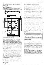
Fasten the ceiling mounting frame in ceiling anchor
pieces with four size M8 threaded rods. Adjust the
length of rods so that they will extend no more than
30 mm below the inner surface of the ceiling mounting
frame. If they extend further, they will interfere with the
upper section of the ventilation unit. Install at least three
threaded rods in the corners of the ceiling mounting
frame. To avoid a possible collision with the ducts, one
of the threaded rods can be located in the hole next to
the corner. (Threaded rods and nuts accessories are not
included in the delivery.)
Screw in the M8 nuts onto the threaded rods to such a
height that the ceiling mounting frame will be horizon-
tal when the top of the frame goes against the nuts. Fit
the ceiling mounting frame through the selected holes
towards the nuts of the threaded rods and lock the
frame into position with nuts from underneath. Adapt
the installation height so that the locking screws in the
ceiling mounting frame’s front section will extend suf-
ficiently far below the ceiling.
The ceiling mounting frame must not be used as
part of a support structure for the ducts
, the duct
support must be sufficient even without the support
effect provided by the ceiling mounting frame.
Before you lift the ventilation unit into position, back
off the two screws at the front of the ceiling mounting
frame so much that the screw heads stick out approx. 2
cm. In addition, route the power supply and data cables
through the ceiling mounting frame.
To make it easier to lift the ventilation unit, the inspec-
tion cover can be removed and the heat exchanger
can be dismantled from the unit. See the ”Servicing”
Section.
Lift the ventilation unit up against the ceiling mounting
frame so that all four locking hooks, which are locate
don top of the ventilation unit, engage into position.
There are two catches on each locking hook. The pur-
pose of the upper one is to secure the ventilation unit to
facilitate connection to the ducts and the wiring of the
electric cables.
Now lift up the ventilation unit onto the lower hooks
when the unit is in the correct position in relation to the
ducts and the power cables have been routed into the
ventilation unit. When the hooks are locked, the spring-
loaded screws of the front section of the ceiling mount-
ing frame extend outward. Finally, lock the ventilation
unit into position by tightening the screws.
Be careful not to press on the screws, because doing
so will disengage the ventilation unit. It is not per-
missible to walk under the ventilation unit during
installation.
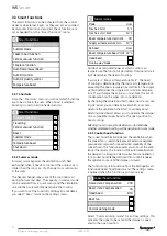
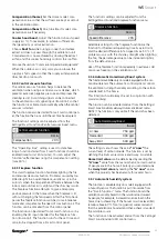
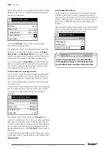
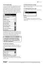
2.1.3 Mounting on a base
The ventilation unit can also be mounted on the floor
using a base which is available as an accessory.
The ventilation unit’s base is mounted horizontally by
using the adjuster feet. In order to facilitate lifting the
ventilation unit onto the base, the heat exchanger and
front cover can first be dismantled from the from the
ventilation unit.
Installation of the condensate hose can be done when
the ventilation unit is on the base, by loosening the
front edge that is secured with screws. There are open-
ings for the condensate hose on the sides of the base.
60
155
441
38
208
389
559
168
432
24
597
597
Ceiling mounting frame, dimensions
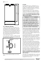
Important
If you improperly tighten the ceiling
mounting frame, this could turn the frame
and the ventilation unit will not have room
inside the frame.
!
!
Содержание CASA SMART W9 Econo
Страница 1: ...W5_e_EN t CASA W5 SMART Installation commissioning and maintenance instruction TECHNICAL MANUAL...
Страница 11: ...11 W5 Smart All rights to changes reserved 2020 11 19...
Страница 27: ...27 W5 Smart All rights to changes reserved 2020 11 19...
Страница 35: ...35 W5 Smart All rights to changes reserved 2020 11 19...


