ThermShield Standard Square/Rectangular Installation Guide
24
Swegon reserves the right to alter specifications. 20210615 - L00010
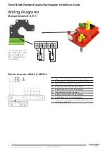
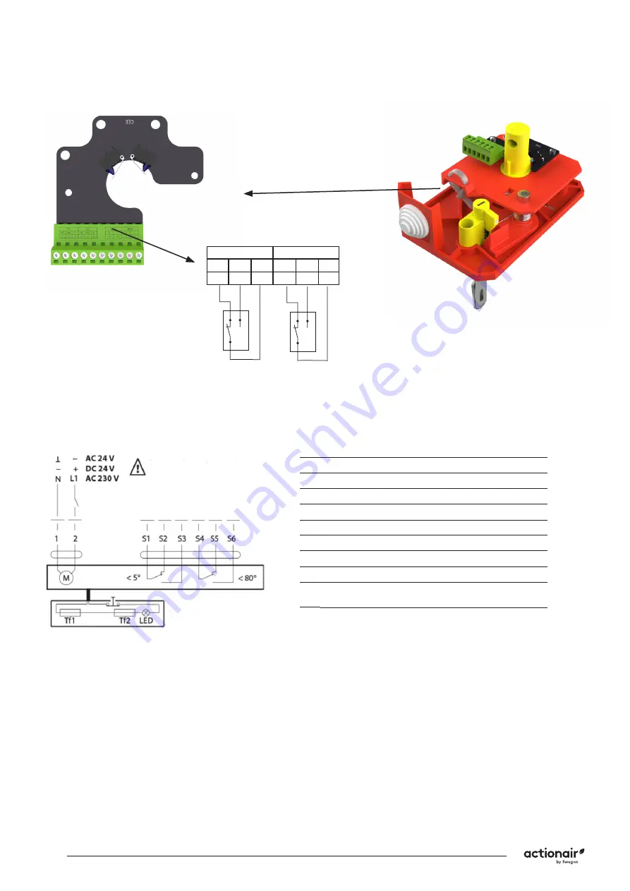
Wiring Diagrams
Manual Actuators R, R-S
FC = Limit switch - end
DC = Limit switch - start
NO = normally open
NF = normally closed
C = common
FC
DC
NF NO
C
NF NO C
11 12 13 14 15 16
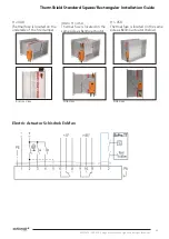
1
negative (direct-current) or neutral (alternating current)
2
positive (direct-current) or faze (alternating current)
S1 common micro switch closed damper
S2 normally closed micro switch closed damper
S3 normally open micro switch closed damper
S4 common micro switch open damper
S5 normally closed micro switch open damper
S6 normally open micro switch open damper
Tf temperature sensor on the outer side of the duct (ambient
temperature) max. 72 °C
Electric Actuator M24-S & M230-S

