USER GUIDE
Ɩ
EM8500 SERIES
Copyright
2016, EM Microelectronic-Marin SA
EMDVK8500-MN01, Version 2.0, 5-Jul-16
32
420005-A01, 3.0
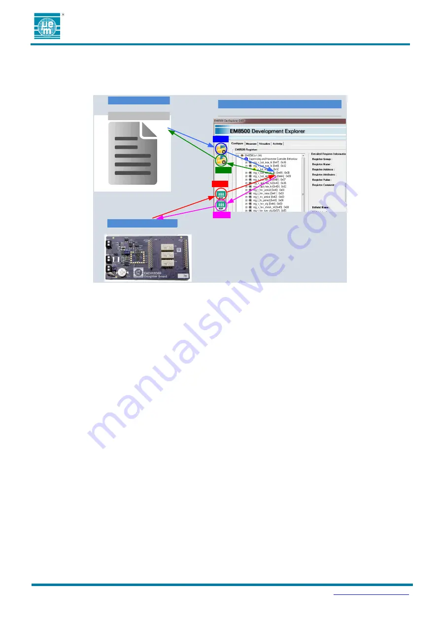
Four different buttons (Load, Save, Read and Write) are used to transfer and update the content from one type of
configuration to another.
Figure 10-4 EM8500 DevExplorer configuration flow description) shows the different possible actions and data flow
transfers.
*.EM8500CFG
Configuration File
User interface
EM8500 Registers Configure window
EM8500
Device configuration
Load EM8500CFG
into user interface
EM8500 Registers
Configure
window
Save user interface
EM8500 Registers
Configure window
into EM8500CFG
Update user interface EM8500 Registers
Configure window with EM8500 device
configuration
LOAD
SAVE
READ
WRITE
Write EM8500 device configuration from
the user interface EM8500 Registers
Configure window.
Figure 10-4 EM8500 DevExplorer configuration flow description
It is important to note that:
Ɩ
the
“EM8500 Registers” view is not necessarily reflecting the physical content of the EM8500 EEProm
memory device and vice-versa.
Ɩ
the
“EM8500 Registers” view is not necessarily reflecting the content of the EM8500CFG file and vice
versa
10.2 MEASURE WINDOW DESCRIPTION
This menu allows the user to control the different switches/selectors and to start measurements.
Figure 10-5 EM8500 DevExplorer measure window description) describes these selections.
The “Configure mode” and the “Application mode” (described in the paragraph 5) can be selected through the
selector called “Mode selector” in the Figure 10-5 EM8500 DevExplorer measure window description.
In Configure mode, the user is able to:
Ɩ
Use the Configure window to configure and access the EM8500 device
Ɩ
Control the HRV, STS and LTS switches (for hardware security reason some sequences are automatically
managed or controlled by the tool)
Ɩ
Select (for configure mode) communication bus (I
2
C or SPI).
Ɩ
Run an INIT sequence to initialize the system
Ɩ
Start the ADC acquisition


