background image


26 


6.2. 

Error Codes and Their Meanings 


Code Meaning 

Er05 

Battery weak or faulty 

Er06 

Output short-circuited 

Er07 

EPO mode 

Er11 

UPS over-temperature 

Er12 

Inverter overload 

Er24 

Utility low

< 160 V

or battery disconnected 

Er28 

Bypass overload 


6.3. 

Maintenance 

     1. Clean the dust from the ventilation openings and intakes on the rear panel.   

2. Turn off the UPS and wipe the casing with a damp cloth.


Be careful to 

avoid getting water in the UPS.   

3. Periodically unplug the power cord of the UPS from the wall receptacle to 

test the condition of the batteries. Be sure you have saved your data in 
any open computer applications before you proceed with this battery test.   


27


7. Communication 

Software 


7.1. 

Hardware Setup 


1. 

Decide whether to use RS-232 communication or USB communication. 

(For 

optional interface cards please refer to Chapter 8.)


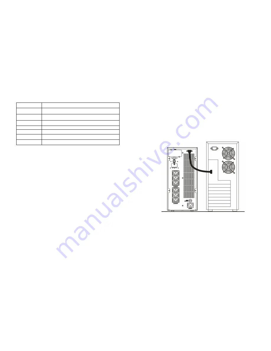
2. Connect a male RS-232 connector or a USB cable* to the UPS 

communication port. Connect the female RS-232 connector or the other 
end of the USB cable to the computer. 


*Note: RS-232 and USB cables are optional. 


7.2. 

Software Installation 


Please refer to the software user’s manual. 


Содержание 1K

Страница 1: ... 15 4 2 Selecting Installation Position 15 4 3 Operation 16 5 UPS Operation Under Various Conditions 18 5 1 UPS System Block Diagram 18 5 2 When Utility is Normal 19 5 3 When Utility is Abnormal or Absent 20 5 4 Overload Condition 21 5 5 Inverter Failure 22 5 6 Overheating 22 5 7 Inverter Current or Voltage Out of Tolerance 22 6 Maintenance Guide 23 6 1 Troubleshooting 23 6 2 Error Codes and Their...

Страница 2: ...salty environments can damage any UPS Install the UPS indoors as it is not designed for installation outdoors 7 To prevent overheating of the UPS keep all ventilation openings free from obstruction and do not place anything on top of the UPS Keep the UPS rear panel 20 cm away from the wall or other obstructions 8 Install the UPS in a ventilated area ideally exchanging 5 m 3 of air per hour because...

Страница 3: ...ne wave topology yields excellent overall performance 3 The high crest factor of the inverter handles all high in rush current loads without the need to upgrade the power rating 4 User friendly plug and play design allows hassle free installation 5 Built in maintenance free sealed batteries minimize the need for after sales service 6 To protect the unit from overloading the UPS will automatically ...

Страница 4: ...ass Sensitivity Low many selectable output voltages 15 and ii Bypass Sensitivity High many selectable output voltages 10 For example if the output voltage setting is 230 V the Bypass Sensitivity Low range is 230 V 15 i e 195 5 264 5 VAC 8 The UPS provides numerous configurable output voltages to match various system voltages 9 The UPS is designed to comply with various stringent international stan...

Страница 5: ...lines are connected wrongly or high neutral ground voltage 2 In Battery and Load Function Mode indicates load capacity is 100 3 In Error Code Function Mode indicates Error Code 8 Outlet1 LED 1 Indicates UPS Outlets 1 are enabled and ready to supply loads This function is optional 2 In Battery and Load Function Mode indicates load capacity is 75 3 In Error Code Function Mode indicates Error Code 4 ...

Страница 6: ...erter Frequency synchronizing range 7 Com Port Select the COM port of an attached PC 8 Click on Write to confirm the configuration settings The UPS will beep twice to acknowledge a successful change 9 Turn off the UPS after changing settings to make sure that the new values are written into EEPROM successfully then restart the UPS to enable the new settings Note CF50 CF60 Frequency Converter mode ...

Страница 7: ...n off the UPS and remove the input source to make sure that those new parameters are written into EEPROM successfully then re start the UPS to enable the new settings 7 Manual Control Switch Click On or Off to manually enabled or disabled the programmable outlets overriding all previous settings 13 3 4 Communication Port Explanation The UPS is equipped with a true RS 232 communication port as stan...

Страница 8: ...owing standard package contents in addition to the UPS itself A User Manual B IEC output cables for UPS with IEC sockets only C IEC input cables for UPS with IEC sockets only 4 2 Selecting Installation Position The UPS is heavy Select a location sturdy enough to support the UPS weight To ensure proper operation and long operating life position the UPS according to the following requirements 1 Keep...

Страница 9: ...EDs and will shine after 1 5 seconds and the buzzer will pulsate to indicate successful power on Note Ensure that the UPS batteries are pre charged for at least four hours by simply connecting the AC power cord to the utility receptacle 17 4 3 1 3 Shutdown 1 Shutdown in AC Mode Press and hold the OFF button for five seconds until the buzzer beeps The UPS will cut the power supply to the outlets Th...

Страница 10: ... voltage or absent Rectifier and charger stop operating Battery discharges via DC DC boost circuit and supplies Inverter Loads continue to receive supply from Inverter Alarm buzzer beeps UPS now in battery mode LED off LED illuminated Utility abnormal or absent or battery voltage low Rectifier and charger stop operating Battery discharges via DC DC boost circuit and supplies Inverter Alarm buzzer ...

Страница 11: ...tion of the UPS will cut off the battery supply at a preset threshold to avoid over draining the batteries 4 The UPS will restart automatically when the utility is available with the same status as in Figure 5 2 21 5 4 Overload Condition The operating mode of the UPS when overloading occurs is illustrated as follows RECTIFIER AC DC CONVERTER DC DC CONVERTER INVERTER STATIC SWITCH SSM CHARGER BATTE...

Страница 12: ...e 23 6 Maintenance Guide 6 1 Troubleshooting If the UPS malfunctions during operation please check that all lines are connected properly and that the utility specifications are correct Then check the table below for solutions Should the problem persist please contact your local dealer for assistance Situation Check Items Solution 1 Er05 Er24 1 Check for proper battery connection Measure battery vo...

Страница 13: ...y 1 Do not use the power strip 2 Replace the wall receptacle cord plug Strange noise or smell Immediately shut down the whole system Disconnect the power from the UPS and call for service UPS is unable to provide backup power Check that the battery connectors are fully engaged Allow the batteries to recharge if they are weak If the problem persists after recharging replace the batteries If the pro...

Страница 14: ... unplug the power cord of the UPS from the wall receptacle to test the condition of the batteries Be sure you have saved your data in any open computer applications before you proceed with this battery test 27 7 Communication Software 7 1 Hardware Setup 1 Decide whether to use RS 232 communication or USB communication For optional interface cards please refer to Chapter 8 2 Connect a male RS 232 c...

Страница 15: ...tact 4 Æ Inverter On 5 Æ Battery Low 6 Æ Battery Bad or Abnormal 7 Æ UPS Alarm 8 Æ Common 9 Æ Shutdown UPS positive signal 10 ÆShutdown UPS negative signal 8 3 2 The shutdown function will be activated after 6 25 VDC is applied between pin 9 and pin 10 for 5 seconds 8 3 3 The capacity of each relay contact is 40 VDC 25 mA 8 3 4 Installation Position Optional Slot 8 3 5 Flexible signal output for N...

Страница 16: ...nstallation please refer to the user s manual that came with the card 8 4 2 2 Installation Position Optional slot on rear panel 31 8 4 3 USB The USB communication protocol definition is as below 1 Complies with USB version 1 0 1 5 Mbps 2 Complies with USB HID version 1 0 3 Pin Assignments 8 4 4 EPO Pin Assignments 1 Æ EPO 2 Æ Ground To enable the EPO function short pins 1 and 2 1 Æ VCC 5V 2 Æ D 3 ...

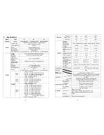
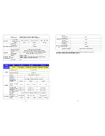
Страница 17: ... 2 seconds shuts down 158 176 for 1 seconds shuts down 177 187 for 0 32 seconds shuts down 188 for 0 16 seconds shuts down Buzzer continuously alarms 33 Line mode 90 90 90 Battery mode 85 85 85 Efficiency ECO mode 96 96 96 Number of batteries 2 4 6 Battery type 12 V 7 2 Ah Sealed non spillage maintenance free lead acid Rated Battery Voltage 24 VDC 48 VDC 72 VDC Backup time half load 10 min 10 min ...

Страница 18: ... 4A 320W 8A 640W Voltage Rating 110 300 VAC Frequency Rating 50 60 Hz INPUT Phase Single phase with ground Number of batteries 2 4 6 Battery type non spillage maintenance free lead acid Rated Battery Voltage 24 VDC 48 VDC 72 VDC Charge Current Max 8 8 A 5 6 A 11 2 A 4 A 8 A Floating Mode Charging Voltage 27 4Vdc 1 54 8Vdc 1 82 2Vdc 1 Bluk Mode Charging Voltage 30 0Vdc 1 60 0Vdc 1 90 0Vdc 1 Battery...

Страница 19: ...36 37 ...

Страница 20: ...38 39 192321172001004 ...

Отзывы: