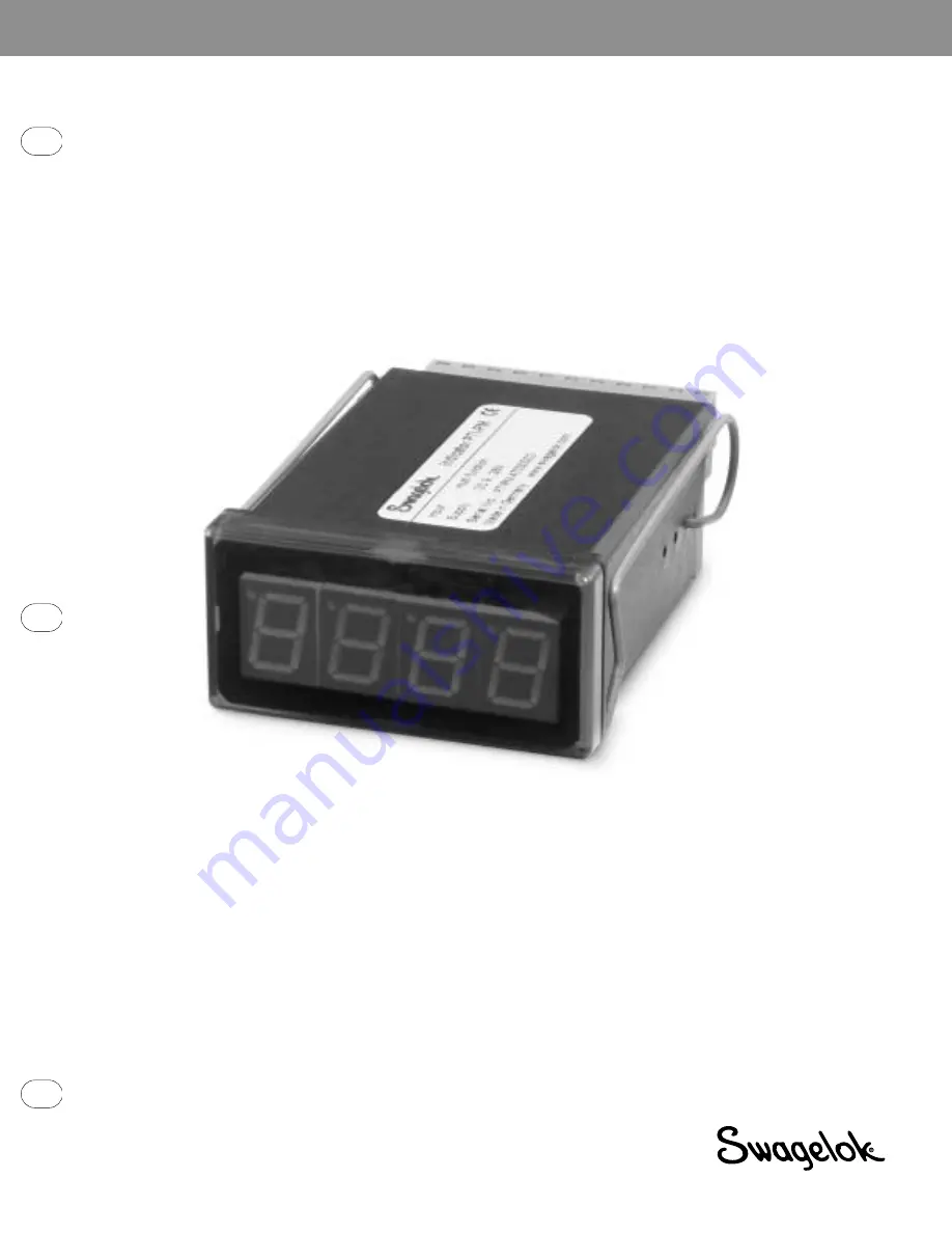
R e m o t e P a n e l M o u n t D i s p l a yM o d e l P T I - P M
www.swagelok.com
O p e r a t i n g I n s t r u c t i o n s
Страница 1: ...Remote Panel Mount Display Model PTI PM www swagelok com Operating Instructions...
Страница 2: ...ing outputs 7 3 4 1 Connection with configured low side switching output NPN output switching to GND 7 3 4 2 Connection with configured high side switching output PNP output switching to Uv 7 3 4 3 Co...
Страница 3: ...es 1 Use within the conditions specified in the Swagelok General Industrial Transducer catalog 2 Always disconnect the device from its power supply before opening it Do not touch any of the device s c...
Страница 4: ...d 3 will increase or decrease in value by one each time the button is touched If the button is held down the value will increase or decrease quickly 4 MS 13 PTI PM E Rev 0 6 04 WEL To configure the PT...
Страница 5: ...mA 8 and 7 6 and 7 0 V 0 V 0 V 3 3 V 3 3 V 10 V 1 V 1 V 1 V 4 V I 10 mA 10 V I 10 mA 20 V Note The contacts 3 5 and 7 are connected internally 3 2 Connection data Do not exceed the limit of the curren...
Страница 6: ...cer Sig 6 10 V 1 V 2 V Supply 9 to 28 V dc Transducer Uv Uv Sig 4 5 7 9 6 10 V 1 V 2 V 4 5 7 9 Supply 9 to 28 V dc 0 4 to 20 mA transducer Supply for transducer Uv Uv Uv Uv 4 5 9 Sig 4 5 7 9 Supply 9...
Страница 7: ...rm condition occurs Note In order to avoid unwanted or wrong switching processes connect the device s switching outputs after you have configured the device s switching outputs properly Connecting con...
Страница 8: ...the input signal SEnS and the measuring unit Unit all settings will be changed to factory default You have to set all the other settings including the settings for zero and span adjustment and switchi...
Страница 9: ...ay when a 0 mA 4 mA or 0 V input signal is attached Confirm the selected value by pressing button 1 The display shows di Lo again Press button 1 again The display will show di Hi Display High high dis...
Страница 10: ...2 point controller 2P 5 1 3 point controller digital 2 point controller 5 1 2 point controller with Min Max alarm digital 2 point controller 2P AL 5 2 Min Max alarm common Max alarm AL F1 5 3 Min Max...
Страница 11: ...isplay Kind of Alarm Output Note nPn Low Side NPN open collector switching GND High Side PNP open collector switching Ub Push Pull Switching output is closed connected to GND as long there is no alarm...
Страница 12: ...e will display 1 on turn on point of output 1 Use button 2 or button 3 to set the desired value The device s output 1 will turn ON Press button 1 to confirm your selection The display shows 1 on again...
Страница 13: ...on Note The unit of the value will be in sec The device will turn on the alarm after the minimum or the maximum alarm value was active for the delay time you have set Press button 1 to confirm the del...
Страница 14: ...ithout span adjustment the device would display 1020 with span adjustment of 102 Press button 1 to confirm the selection of the span adjustment The display shows SCAL again Example Connecting a 4 to 2...
Страница 15: ...ecessary Err 4 Values below display range Indicates that display value is below the valid display range of the device 1999 digit Possible causes Incorrect scale Remedies The error message will be rese...
Страница 16: ...Swagelok TM Swagelok Company 2004 Swagelok Company September 2004 R0 MS 13 PTI PM E...