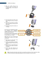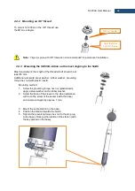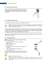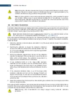
29
SV 200A User Manual
To uncover the control panel, unscrew the coin-
operated screw (with your fingers, or the first turn
with the coin and then the fingers) slightly to the stop.
If the instrument is in vertical position the flap should
slide down and its upper (rectangular) part should
slide out from under the eaves. If the flap does not
slide down, slightly press the lower part with your
finger and move it down. Then turn the flap clockwise
(or counter-clockwise).
Note:
The coin-operated screw should be loosened using, for example, a coin and then
unscrewed with fingers until it stops. Opening the flap with the screw left in the intermediate
position may damage the varnish of the casing.
To close the control panel, turn the flap so that its upper, rectangular part jumps into the notch of the casing.
If the lower part of the flap is pressed against the head of the screw through the inner spring, it should be
lightly pressed (so as not to damage the lacquer
on the flap). Move the flap up (with your finger) by pressing
it all the time so that the upper part of the flap is hidden under the notch. Tighten the screw to the stop
(finger, possibly the last rotation by the coin) by pressing the flap all the time.
Note: Operate carefully so that the metal edges of the flap do not damage the varnish on the
surface of the casing, especially at the edge of the notch.
Five control keys enable following functions:
•
turning On/Off the instrument when holding 3 sec,
•
opening a position in the menu list,
•
entering editing mode for the parameter,
•
confirming made changes,
•
changing main results/status views,
•
returning to the upper menu list,
•
exiting the current parameter edition without saving changes,
•
changing measurement/status views,
•
starting or stopping measurements,
•
resetting the instrument when holding 10 sec,
•
starting the calibration,
•
staring the system check,
,
•
selecting position in the menu or parameter list,
•
changing the parameter value,
•
opening the Menu by pressing both keys simultaneously,
•
changing profiles/results in the measurement view.
Note: Pressing and holding
and
keys simultaneously during the instruments
switching on longer than 3 seconds, starts the BOOTSTRAP mode of SV 200A, used for
firmware update (see Chapter
Note: Pressing and holding
during the firmware booting when Svantek icon appears,
enables loading factory settings before the instrument’s start. This Factory Settings function
will reset all settings including communication one.
Содержание SV 200A
Страница 123: ...123 SV 200A User Manual Appendix A REMOTE CONTROL firmware revision 1 x x Under development ...
Страница 153: ...153 SV 200A User Manual Free Field Frequency response of SV 200A ...
Страница 164: ...164 SV 200A User Manual 250 Hz 315 Hz 90 deg 0 deg 90 deg 0 deg 400 Hz 500 Hz 90 deg 0 deg 90 deg 0 deg ...
Страница 165: ...165 SV 200A User Manual 630 Hz 800 Hz 90 deg 0 deg 90 deg 0 deg 1000 Hz 1250 Hz 90 deg 0 deg 90 deg 0 deg ...
Страница 166: ...166 SV 200A User Manual 1600 Hz 2000 Hz 90 deg 0 deg 90 deg 0 deg 2240 Hz 2500 Hz 90 deg 0 deg 90 deg 0 deg ...
Страница 167: ...167 SV 200A User Manual 2800 Hz 3150 Hz 90 deg 0 deg 90 deg 0 deg 3550 Hz 4000 Hz 90 deg 0 deg 90 deg 0 deg ...
Страница 168: ...168 SV 200A User Manual 4500 Hz 5000 Hz 90 deg 0 deg 90 deg 0 deg 5600 Hz 6300 Hz 90 deg 0 deg 90 deg 0 deg ...
Страница 169: ...169 SV 200A User Manual 7100 Hz 8000 Hz 90 deg 0 deg 90 deg 0 deg 8500 Hz 9000 Hz 90 deg 0 deg 90 deg 0 deg ...
Страница 170: ...170 SV 200A User Manual 9500 Hz 10000 Hz 90 deg 0 deg 90 deg 0 deg 10600 Hz 11200 Hz 90 deg 0 deg 90 deg 0 deg ...
Страница 177: ...177 SV 200A User Manual 8 0 kHz 1 1 octave filter 4 0 kHz 1 1 octave filter 2 0 kHz 1 1 octave filter ...
Страница 178: ...178 SV 200A User Manual 1 0 kHz 1 1 octave filter 500 Hz 1 1 octave filter 250 Hz 1 1 octave filter ...
Страница 179: ...179 SV 200A User Manual 125 Hz 1 1 octave filter 63 0 Hz 1 1 octave filter 31 5 Hz 1 1 octave filter ...


