Stepping Systems
For a complete user manual, please visit www.automationdirect.com
Data Sheet: STP-MTRD-QSP, 1st Ed – 03/12/2018
Step 8:
Optionally, you can test motor operation by activating
switch 4 in the “SETUP” DIP switch bank to initiate a self
test. The self test continually rotates the motor forward
and backward 2 1/2 revolutions.
Additional Help and Support
• For product support, specifications, pricing and installation troubleshooting, a Hardware User
Manual can be downloaded from the Online Documentation area of the AutomationDirect web
site.
• For additional technical support and questions, call our Technical Support team
@ 1-800-633-0405 or 770-844-4200.
Step 7:
Optional settings in the “SETUP” DIP
switch bank–the default settings for these
switches are typically sufficient. See the User
Manual for details on these functions.
A.
[Switch 5] Step Pulse Noise Filter
B.
[Switch 6] Step Smoothing Filter
C.
[Switch 8] Step Pulse Type (Step/
Direction is default)
6
ON
6
OFF
SMOOTHING
8
CW PULSE/
CCW PULSE
STEP/
DIR
8
5
150
KHZ
5
2.0
MHZ
4
ON
4
OFF
SELF TEST
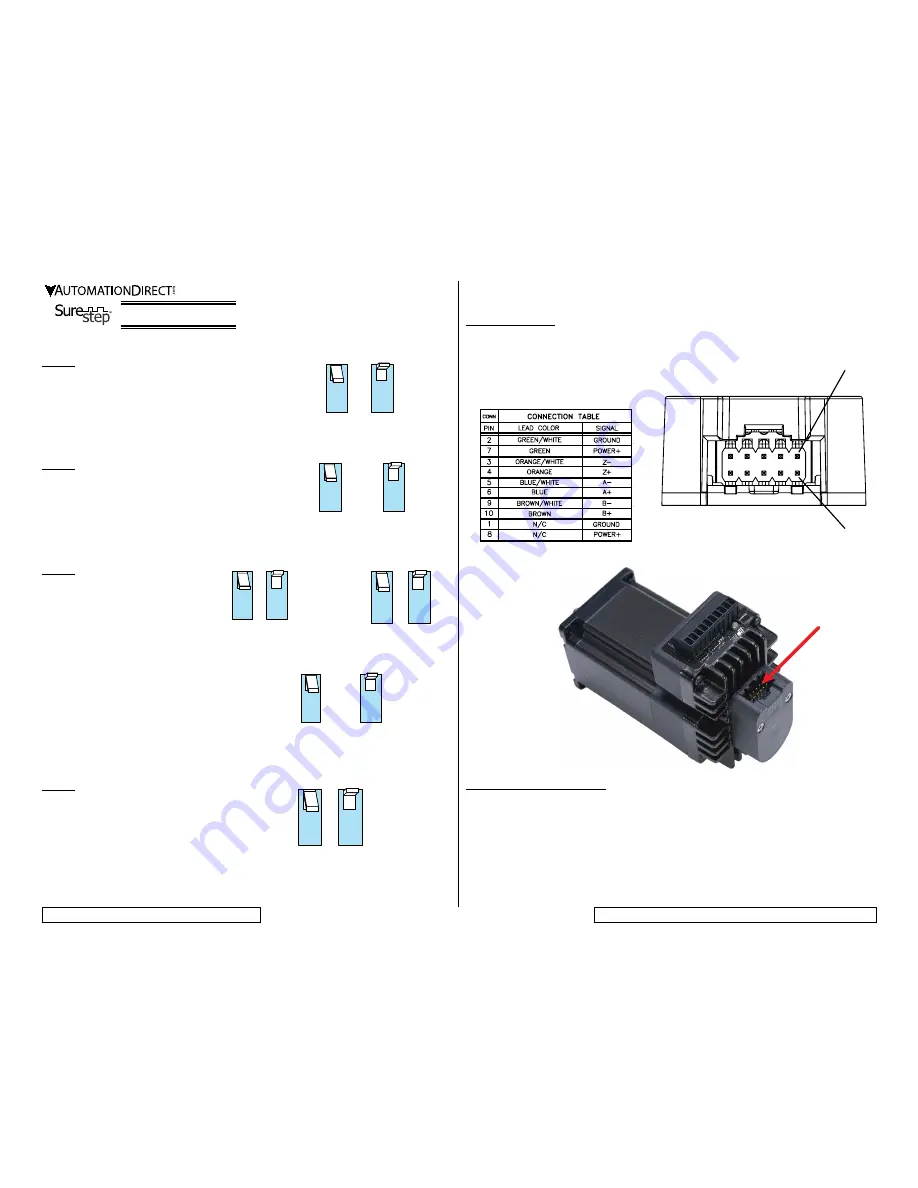
Optional Encoder:
An optional encoder is available pre-mounted on “E” models. The standard encoder is a 1000ppr, Differential
line driver encoder. See below for pinouts and wire colors for the replacement cable (STP-CBL-EAxx) and
included cable with the STP-MTRD.
For more information on the encoder, please
see the Sure Step User Manual. Replacement
encoder part number is STP-MTRA-ENC1.
PIN 1
PIN 2
Step 5:
In the “SETUP” DIP switch bank, set the motor’s idle
current using switch 3. This is the percentage of running
current that the motor will use when the shaft is not
rotating. Choose 90% for maximum holding torque or
50% to reduce motor heating.
Step 6:
In the “SETUP” DIP switch bank, select the load-to-
motor ratio category using switch 7. This is the ratio of the
effective load inertia to the motor’s own rotor inertia. For
high inertia loads choose 5-10X, and for low inertia loads
choose 0-4X. Setting the proper range for the load will
improve motor smoothness.
3
50%
3
90%
7
5-10X
7
0-4X
Encoder connection
N
ote
: P
iN
1
aNd
P
iN
2
are
iNterNally
coNNected
.
P
iN
7
aNd
P
iN
8
are
iNterNally
coNNected
iNside
the
eNcoder
.


