D
E
L
r
o
l
o
C
s
u
t
a
t
S
n
o
it
p
i
r
c
s
e
D
f
o
r
e
b
m
u
N
D
E
L
r
e
w
o
P
n
e
e
r
G
n
O
n
o
r
e
w
o
P
1
t
s
e
T
w
o
ll
e
Y
n
O
r
o
r
r
e
t
s
e
t
p
o
o
L
s
r
u
c
c
o
1
.t
c
A
/
d
e
e
p
S
n
e
e
r
G
n
O
f
o
s
p
b
M
0
0
1
tr
o
p
d
e
t
c
e
n
n
o
c
)
8
-
1
(
8
g
n
i
h
s
a
l
F
a
t
a
d
r
o
f
s
p
b
M
0
0
1
g
n
i
v
i
e
c
e
r
w
o
ll
e
Y
n
O
f
o
s
p
b
M
0
1
tr
o
p
d
e
t
c
e
n
n
o
c
g
n
i
h
s
a
l
F
a
t
a
d
r
o
f
s
p
b
M
0
1
g
n
i
v
i
e
c
e
r
.l
o
C
/
X
D
F
n
e
e
r
G
n
O
f
o
s
u
t
a
t
s
x
e
l
p
u
D
-l
l
u
F
tr
o
p
d
e
t
c
e
n
n
o
c
)
8
-
1
(
8
g
n
i
h
s
a
l
F
f
o
s
r
u
c
c
o
n
o
i
si
ll
o
C
M
0
0
1
r
o
M
0
1
1. Uplink
The Uplink port is used to connect to other
switches or hubs. The Uplink port is shared with
the port #1.
2. RJ-45 Ports
Eight N-Way Mini RJ-45 STP ports all come with
auto-negotiation and operate at 100/10Mbps for
connection to servers and hubs. All ports can be
configurated for Full/Half-Duplex mode.
3. Power Connector
For the external 7.5V DC power adapter that
connects to power outlet.
Rear Panel
LED Indicators
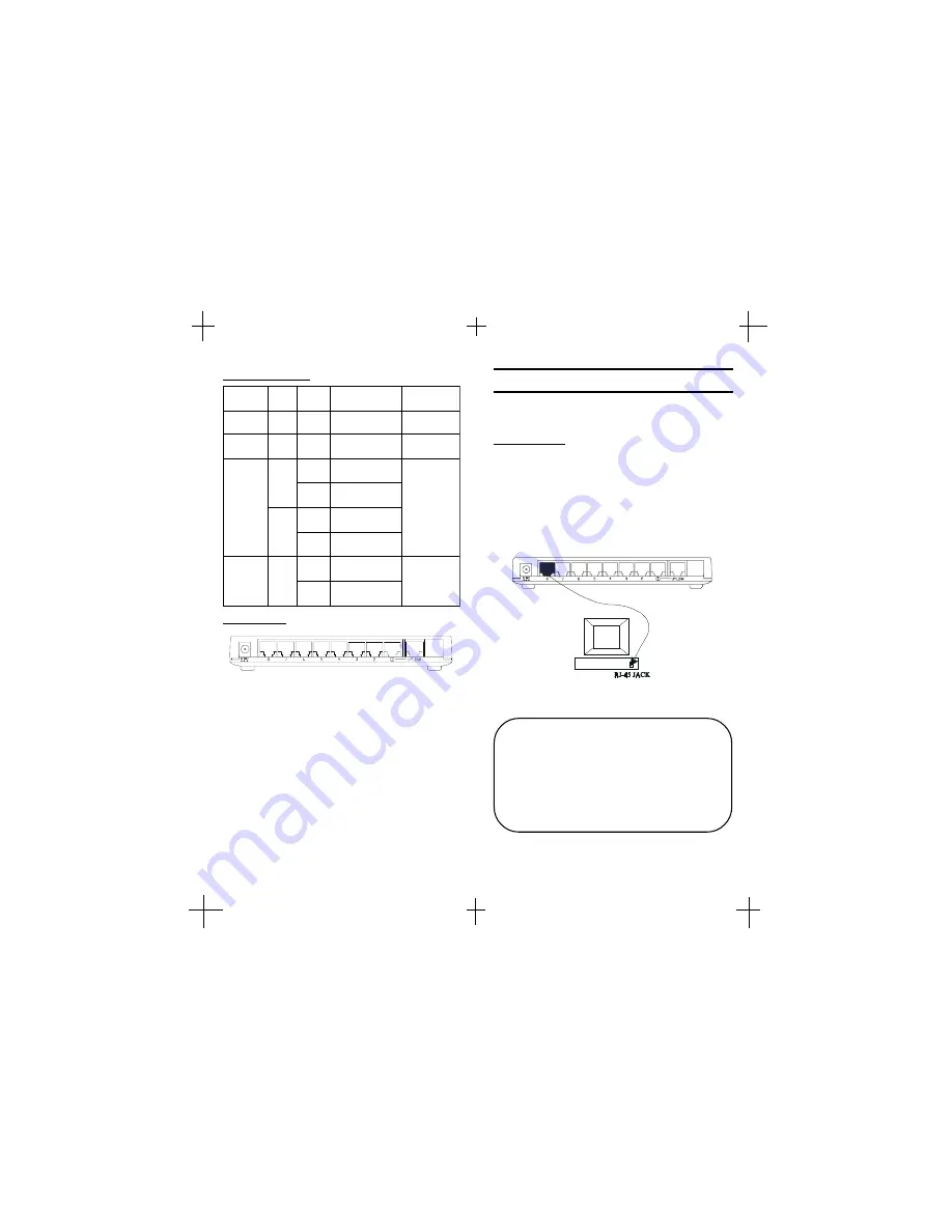
The following figures illustrate the connections of
8-Port N-Way Mini Switch.
PC to Switch
A PC can be connected to the 8-Port N-Way Mini
Switch via a two-pair Category 3/4/5 UTP/STP
straight cable. The PC (equipped with a RJ-45 100/
10Mbps jack) should be connected to any of eight
ports.
The 8-Port N-Way Mini Switch
Note: The LED indicators for PC con-
nection are dependant on the LAN card
capabilities. If LED indicators are not
illuminated after making a proper
connection, check the PC LAN card, the
cable, the N-Way Mini Switch conditions
and the connections.
!
"
Network Connection


