THE FOLLOWING GUIDELINES
APPLY TO ALL MOUNTING
SCHEMES
1. The wire rope may be installed
on the drum in the overwound or
underwound condition, in either
flat plate or rail mounting
scheme.
2. All fasteners used in mounting
the winch should be M12x1.75
with a strength rating of Grade
8.8 or better. All fasteners used in
mounting the winch must comply
with the lengths for material
thicknesses listed in the bolt
length table in the mounting
specifications section.
3. Use only the threaded holes
provided to mount the winch.
Do not drill and tap new hole(s)
as the casting walls may not be
thick enough to support a
winched load.
4. Do not weld the winch or any
parts of the winch.
5. After mounting and tightening
all bolts, place the winch in
freespool and check the drum
rotation. The drum on an improp-
erly mounted winch may bind,
causing poor freespooling and
decreasing winch performance. If
the drum does bind, loosen all
mounting bolts. If the drum now
rotates freely, tighten the bolts a
bit at a time, checking rotation
until the winch is securely fas-
tened. If the drum continues to
bind it is probable that one or
more of the mounting system’s
holes is out of position and
requires correction.
PRECAUTIONS FOR FOOT DOWN
MOUNTING
1. The plate to which the winch
is fastened must be 1/2 inch
(12.7 mm) thick steel minimum
and flat.
2. All four mounting holes in the
bottom of each support casting
must be used to mount the
winch.
PRECAUTIONS FOR RAIL
MOUNTING
1. The angle iron used for the rails
must be 3x3x1/4 (75x75x6 mm) or
larger.
2. All four mounting holes (2 in
each side of each casting) must
be used.
6
PUMP / HORSEPOWER
REQUIREMENTS
The hydraulic system pump
should be capable of delivering
an oil flow of 15 gallons/minute,
(57 litre/minute), continuous. The
pump must be capable of develop-
ing 1800 psi (124 bar) continuous.
The rating of the pump must be
greater than 1,800 psi to account
for line losses. We recommend a
pump rated for 2,500 psi. These
parameters equate to an input
horsepower requirement of 20-25
HP, assuming a 15 to 20%
line loss.
1. The intermittent ratings of 20
GPM and 2250 psi must not occur
simultaneously. The winch motor
will be damaged.
2. If the hydraulic system powering
the winch is capable of delivering
higher flows and pressures than
the winch rating, installation of a
separate flow control and relief
valve to protect the winch circuit
is required.
The winch may be used with
hydraulic systems unable to deliver
the recommended flow or pressure.
Under these conditions the winch
will not perform to specification.
The winch will not operate when
the pressure drops below 800 psi.
Check the flow, pressure and
Performance data (page 4) in this
manual to determine how the line
speed and pull will be affected.
DIRECTIONAL CONTROL VALVE
A spring centered, 4-way directional
control valve should be used to con-
trol the motor’s rotation. The valve,
if manually operated, should have
metering capability.
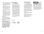
1. The preferred spool configuration
is a floating center. In the neutral
position P is blocked, and A and B
ports are connected to T. (See
schematic on page 8.)
2. An open centered spool may be
substituted for the floating cen-
ter. In the neutral condition all
ports are connected to tank.
Failure to
install and use
the proper valve will effect the
brake operation. Any valve which
does not drain the A and B lines to
tank in neutral will prevent the
brake from engaging.
3. Check the rating for the direc-
tional control valve. An improperly
sized directional valve will greatly
reduce winch performance.
4. The 4-way valve may be fitted
with an integral relief valve.
FILTRATION
The hydraulic system should have a
return line filter with a rating of 10
to 40 microns.
HYDRAULIC FLUID
Any high grade, anti-wear, petro-
leum based hydraulic fluid with a
viscosity rating not less than 100
SUS may be used. For maximum
motor performance and life, the
operating fluid temperature must
be below 180 degrees Fahrenheit
(82 degrees Centigrade).
HOSES
Hoses should have working pres-
sure rating of 3000 psi (200 bar)
or better.
1. For proper winch performance use
of hoses with an inside diameter
of 3/4 inch, (19 mm), is required.
H Y D R A U L I C S Y S T E M
R E Q U I R E M E N T S /
C O M P O N E N T S
C O N T R O L C I R C U I T
7


