Owners Manual 5-201-001 Issue 1
8
Page
04
MAINTENANCE & USE
TIPS FOR EXTENDING THE LIFE OF YOUR WINCH
1.
Note
: Installing the wire rope is not included in the running-in
period. Check tightness of all mounting bolts after running-in
period.
2.
Keep a tightly wound rope drum
. Do not allow the windings
on the drum to become loosely wound. A loosely wound spool
allows a rope under load to work its way down into the layers of
the wire rope on the drum. When this happens, the lower layers
become damaged and the rope may become wedged within the
body of the windings. To prevent this problem, keep tension on
the rope at all times. A good practise is to rewind the rope under
tension after each use.
3.
Prevent kinks before they occur
.
a) This is a start of a kink. At this
time, the rope should be
straightened.
b) The rope was pulled and the
loop has tightened to a kink. The
rope is now permanently
damaged.
c) The result of kinking is that
each strand pulls a different
amount causing the strands under
greatest tension to break and
reduce load capacity of the wire
rope.
4.
Use a snatch block for heavy loads
. To keep wear to a
minimum, use a snatch block to double line heavy loads. Double
lining reduces the work required of the gears by one half which
in turn reduces wear.
5. The pull required to start a load moving is often much greater
than the load to keep it moving. Try to avoid stopping and
starting during a pull.
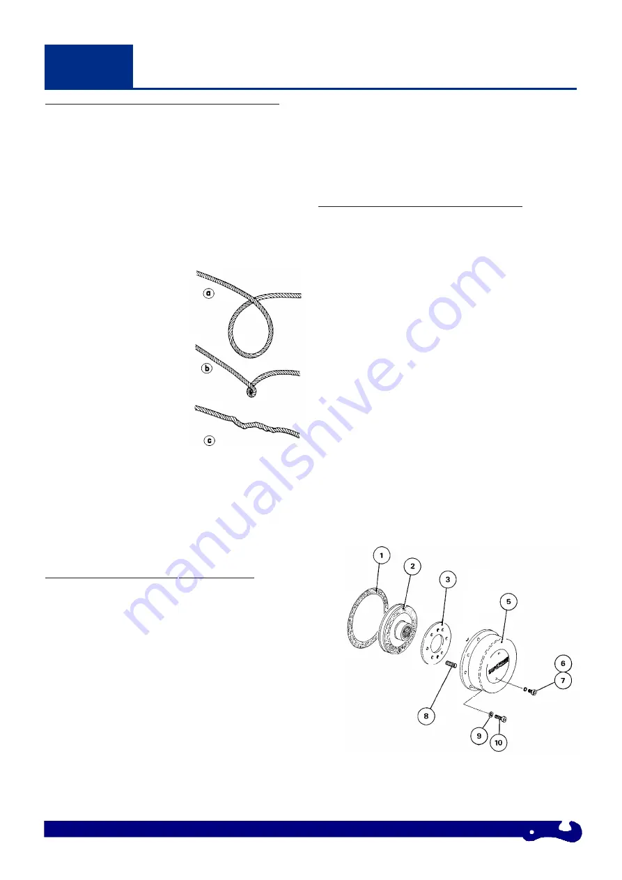
FRICTION PLATE ASSEMBLY REPLACEMENT
1. Drain gearbox oil.
2. Remove two screws, Item 7, in Clutch Cover, Item 5.
3. Replace with two screws, M5 x 0.8 pitch x 40mm long,
shortened to 38mm long.
4. Unscrew six screws, Item 10, and remove Clutch Cover, Item 5
complete with Clutch Plate, Item 3.
Do not remove clutch plate from clutch cover.
5. Slide Friction Plate Assembly, Item 2, from Input Shaft.
6. Replace Friction Plate Assembly, Item 2, ensuring that boss is
facing away from gearbox.
Ensure Roll Pins in Clutch Housing Cover (Item 5), align holes
in clutch plate.
7. Replace gasket, Item 1, and Clutch Cover Assembly.
8. Tighten six screws, Item 10.
9. remove two screws securing the Clutch Plate to Clutch Cover,
and replace two screws, Item 7, complete with seals.
CLUTCH SPRING REPLACEMENT/REMOVAL
1. Follow steps 1 to 4 under the procedure for Friction Plate
Assembly Replacement, described above.
2. Slacken the two Clutch Plate holding screws, carefully. Remove
the Plate, Item 3, to reveal six springs, Item 8.
3. Replace springs.
4. Replace Clutch Plate, Item 3, ensuring roll pins, Item 4, align
with holes in Clutch Plate.
5. Replace the two Clutch Plate holding screws, tighten to draw
plate down on the springs, ensuring roll pins align with holes in
Clutch Plate.
6. Follow steps 7 to 9 under the procedure for Friction Plate
Assembly Replacement, described above.
Item
Qty
PART No.
Description
1
2
10063
Gasket
2
1
10028
Friction Plate Assembly
Drawn Cup Clutch
3
1
10002
Clutch Plate
5
1
50-90622-01
Clutch Cover Assy
6
2
4-23-063
Thread Seal
7
2
4-36-0601022
Cap Head Screw M6 x 10
8
6*
4-31-1403030403
Spring
9
6
4-51-0623
Spring Washer M6
10
6
4-36-0603022
Cap Head Screw M6 x 30
* Model 5072H = 2 Springs


