Supero SuperWorkstation 5036T-T Скачать руководство пользователя страница 46

5-18

S

uper

W

orkstation 5036T-T User's Manual

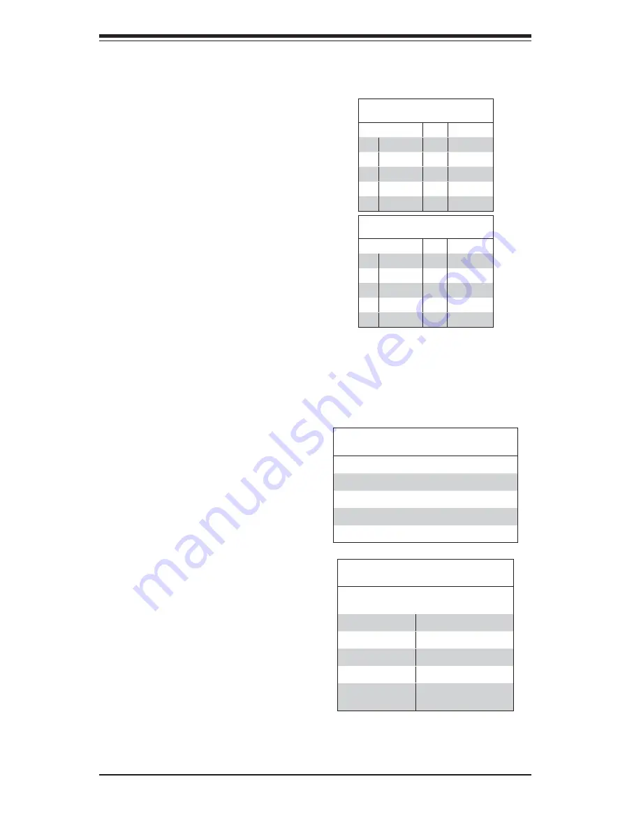
IEEE 1394 Connection

Connectors 1394_1 and 1394_2 

provide connectivity for IEEE 1394 

(Firewire) devices. See the tables on 

the right for pin defi nitions.

1394_1

Pin Defi nitions 

Pin#    Defi n.    

Pin#

Defi n

1

PTPA0+

2

PTPA0-

3

GND

4

GND

5

PTPB0+

6

PTPB0-

7

PWR 1394

8

PWR 1394

10

ZX

1394_2

Pin Defi nitions 

Pin#    Defi n.    

Pin#

Defi n

1

PTPA1+

2

PTPA1-

3

GND

4

GND

5

PTPB1+

6

PTPB1-

7

PWR 1394

8

PWR 1394

10

ZY

Universal Serial Bus (USB)

Eight Universal Serial Bus ports (USB 

0~3, USB 4/5, USB 6/7) are located 

on the I/O back panel. USB Ports 4/5 

are located below LAN Port1 port. 

USB 6/7 are below LAN Port2. An 

additional four USB connections (USB 

8, USB 9 and USB 10/11) are used 

to provide front chassis access. USB 

8 and USB 9 are Type A connectors. 

(USB cables not included). See the 

tables on the right for pin defi nitions.

Back Panel USB 0~3, 4/5, 6/7

Pin Defi nitions

Pin#   Defi nition    Pin#       Defi nition

1

+5V

5

+5V

2

USB_PN1

6

USB_PN0

3

USB_PP1

7

USB_PP0

4

Ground

8

Ground

Front Panel USB 8, 9, 10~11

Pin Defi nitions

      USB 8, 9, 10   
Pin #      Defi nition

      USB 11
Pin #      Defi nition

1

+5V

6

+5V

2

USB_PN2

7

USB_PN3

3

USB_PP2

8

USB_PP3

4

Ground

9

Ground

5

No Con-
nection

10

Key

Содержание SuperWorkstation 5036T-T

Страница 1: ...SUPER SuperWorkstation 5036T T USER S MANUAL Revision 1 0a...

Страница 2: ...h the limits for a Class B digital device pursuant to Part 15 of the FCC Rules These limits are designed to provide reasonable protection against harmful interference in a residential installation Thi...

Страница 3: ...r provides a checklist of the main components included with the system and describes the main features of the Super X8SAX serverboard and the SC733TQ 465 chassis Chapter 2 Installation This chapter de...

Страница 4: ...vanced Chassis Setup Refer to Chapter 6 for detailed information on the SC733TQ 465 mid tower chassis You should follow the procedures given in this chapter when installing removing or reconfiguring S...

Страница 5: ...v Preface Notes...

Страница 6: ...ackplane 1 3 Cooling System 1 3 1 4 Contacting Supermicro 1 5 Chapter 2 System Setup 2 1 Overview 2 1 2 2 Unpacking the System 2 1 2 3 Setting Up the System 2 2 Checking the Motherboard Setup 2 2 Chec...

Страница 7: ...stalling Memory Modules 5 8 Installing Removing DIMMs 5 8 Order of Populating DIMM Slots 5 9 5 7 Adding PCI Add On Cards 5 10 5 8 Serverboard Details 5 11 X8SAX Quick Reference 5 12 5 9 Connector Defi...

Страница 8: ...isable 5 21 USB Wake Up Enable Disable 5 22 IEEE 1394a Enable Disable 5 22 5 11 Onboard Indicators 5 23 LAN1 2 LEDs 5 23 Onboard Power LED LE1 5 23 5 12 Floppy IDE and SATA Ports 5 24 SATA Ports 5 24...

Страница 9: ...tility 7 1 How To Change the Configuration Data 7 1 Starting the Setup Utility 7 2 7 2 Main Setup 7 2 7 3 Advanced Setup Configurations 7 4 7 4 Security Settings 7 20 7 5 Boot Configuration 7 21 7 6 E...

Страница 10: ...Notes x SuperWorkstation 5036T T User s Manual...

Страница 11: ...addition to the serverboard and chassis various hardware components have been included with the SuperWorkstation 5036T T as listed below One 1 cooling fan FAN 0076L4 One 1 exhaust fan FAN 0077L4 or F...

Страница 12: ...ame size and speed should be used See Chapter 5 for details Serial ATA A SATA controller is integrated into the South Bridge ICH10R section of the chipset to provide a six port Serial ATA subsystem wh...

Страница 13: ...The control panel on the SuperWorkstation 5036T T provides you with system monitoring and control LEDs indicate power on network activity hard disk drive activity and overheat conditions The control p...

Страница 14: ...TSB43AB22A COM1 COM2 Floppy KB MS SPI SPI EEPROM LGA1366_Processor Tylersburg 36S FAN x 6 ICH10R LPC I O PCI_32_BUS DMI INTEL 82574L PCI E_X1 PCI E_X1 RJ45 RJ45 PCI E x16 Slot Gen 2 PCIE_x16 PCIE_x4...

Страница 15: ...per Micro Computer B V Het Sterrenbeeld 28 5215 ML s Hertogenbosch The Netherlands Tel 31 0 73 6400390 Fax 31 0 73 6416525 Email sales supermicro nl General Information support supermicro nl Technical...

Страница 16: ...1 6 SuperWorkstation 5036T T User s Manual Notes...

Страница 17: ...m with the carrier who delivered it Decide on a suitable location for setting up and operating the SuperWorkstation 5036T T It should be situated in a clean dust free area that is well ventilated Avoi...

Страница 18: ...m board The processor should have its own heatsink attached See Chapter 5 for instructions on processor installation Check the system memory 3 Your system may have come with system memory already inst...

Страница 19: ...Chapter 2 System Setup 2 3 Figure 2 1 Accessing the Inside of the 5036T T...

Страница 20: ...12 cm fan that is built in to the power supply The system component layout was carefully designed to promote sufficient airflow throughout the chassis Also note that all power and data cables have bee...

Страница 21: ...l panel This chapter explains the meanings of all LED indicators and any appropriate response you may need to take 3 2 Control Panel Buttons There are two push buttons located on the front of the chas...

Страница 22: ...Indicates power is being supplied to the system s power supply units This LED should normally be illuminated when the system is operating HDD Channel activity for all HDDs This light indicates SATA d...

Страница 23: ...ve Carrier LEDs Each Serial ATA drive carrier has two LEDs Green When illuminated the green LED on the front of the SATA drive carrier indicates drive activity A connection to the SATA backplane enabl...

Страница 24: ...3 4 SUPERWORKSTATION 5036T T User s Manual Notes...

Страница 25: ...ith the operating system first and then unplug the power cords of all the power supply units in the system When working around exposed electrical circuits another person who is familiar with the power...

Страница 26: ...ng fan This product may be connected to an IT power system In all cases make sure that the unit is also reliably connected to Earth ground Serverboard Battery CAUTION There is a danger of explosion if...

Страница 27: ...PCBs come into contact with your clothing which may retain a charge even if you are wearing a wrist strap Handle a board by its edges only do not touch its components peripheral chips memory modules o...

Страница 28: ...t be taken to assure that the chassis cover is in place when the 5036T T is operating to assure proper cooling Out of warranty damage to the system can occur if this practice is not strictly followed...

Страница 29: ...to handle them very carefully see previous chapter To prevent the serverboard from bending keep one hand under the center of the board to support it when handling The following measures are generally...

Страница 30: ...the back lip of 1 the top cover of the chassis then pull the cover off The X8SAX requires a chassis big enough to support a 12 x 10 2 serverboard such as Supermicro s SC733TQ 465 Make sure that the I...

Страница 31: ...SATA drive data cable I SATA0 I SATA3 Control Panel cable JF1 SGPIO cable SGPIO1 Important Make sure the the cables do not come into contact with the fans Connecting Power Cables The X8SAX has a 24 p...

Страница 32: ...Vcc Vcc Vcc Vcc Reset Button Power Button Ground x Key Power On LED HDD LED NIC1 LED NIC2 LED OH Fan Fail LED Power Fail LED Ground Ground 2 1 20 19 1 Keyboard Purple 11 USB Port 6 2 PS 2 Mouse Green...

Страница 33: ...nstall the serverboard into the chassis before you install the CPU heatsinks When receiving a serverboard without a processor pre installed make sure that the plastic CPU socket cap is in place and no...

Страница 34: ...against the surface of the socket or its pins to avoid damaging the CPU or the socket With the CPU inside the socket in 4 spect the four corners of the CPU to make sure that it is properly installed O...

Страница 35: ...the CPU or the heatsink However if you do need to uninstall the heatsink please follow these instructions to avoid damaging the CPU or the CPU socket Installation and Removal of the Heatsink Uninstall...

Страница 36: ...Ms Insert the desired number of DIMMs into the memory 1 slots starting with DIMM 1A For best performance please use the memory modules of the same type and same speed in the same bank See the DIMM Ins...

Страница 37: ...to the following Memory Availability Table for details Order of Populating DIMM Slots For memory to work properly follow the table below for the correct order of populat ing the DIMM slots See the mo...

Страница 38: ...he PCI slot shield for the slot you wish to populate 1 Fully seat the card into the riser card slot pushing down with your thumbs 2 evenly on both sides of the card Finish by using a screw to secure t...

Страница 39: ...SATA4 I SATA3 I SATA2 I SATA1 I SATA0 DIMM3A DIMM3B JBT1 USB 10 11 HD Audio 7 1 S PDIF LAN2 USB6 7 USB 0 3 1394_1 USB9 USB8 Audio FP LAN1 USB4 5 Slot 6 PCI E x16 Gen2 Slot 5 PCI E x4 in x8 Gen1 Slot...

Страница 40: ...inition Audio 7 1 Ports CD In Audio CD Input Header COM1 COM2 COM1 2 Serial Port Connectors Fan 1 6 Fan headers Fan 1 CPU fan Floppy Floppy Disk Drive Connector JD1 Speaker Header JF1 Control Panel He...

Страница 41: ...NC 8 PWR_OK 21 5V 9 5VSB 22 5V 10 12V 23 5V 11 12V 24 COM 12 3 3V Reset Button Pin Definitions JF1 Pin Definition 3 Reset 4 Ground Power Button Pin Definitions JF1 Pin Definition 1 PW_ON 2 Ground Seco...

Страница 42: ...nections for the GB LAN port are on pins 11 and 12 of JF1 At tach an LED cable to display network activity See the table on the right for pin definitions OH Fan Fail Indicator Status State Definition...

Страница 43: ...d the PS 2 mouse are located on the I O back panel The mouse port is above the keyboard port See the table on the right for pin definitions Fan Header Pin Definitions FAN1 6 Pin Definition 1 Ground Bl...

Страница 44: ...end state See the table on the right for pin definitions You must also have a WOR card and cable to use this feature Wake On Ring Pin Definitions JWOR Pin Definition 1 Ground Black 2 Wake up Serial Po...

Страница 45: ...o FP header If these jumpers are not installed the back panel line out connector will be disabled and pin 1 of the microphone in will be left floating which can lead to excessive back panel microphone...

Страница 46: ...ports USB 0 3 USB 4 5 USB 6 7 are located on the I O back panel USB Ports 4 5 are located below LAN Port1 port USB 6 7 are below LAN Port2 An additional four USB connections USB 8 USB 9 and USB 10 11...

Страница 47: ...temperature See the table on the right for pin definitions PWR Supply I2 C Pin Definitions SMB_PS Pin Definition 1 Clock 2 Data 3 PWR Fail 4 Ground S PDIF_Out Connector An S PDIF_Out connector is loc...

Страница 48: ...jumper is on both pins and Open means the jumper is either on only one pin or completely removed Connector Pins Jumper Setting 3 2 1 3 2 1 CMOS Clear JBT1 is used to clear CMOS which will also clear a...

Страница 49: ...2 Setting Pins 1 2 Enabled Pins 2 3 Disabled SMBus to PCI PCI E Slots Jumpers JI2 C1 and JI2 C2 allow you to connect the PCI slots to the System Management Bus I2 C The default setting is disabled See...

Страница 50: ...e See the table on the right for jumper settings Note JPUSB1 is used for USB ports 0 7 and JPUSB2 is for Front Panel USB ports 8 9 and 10 11 The de fault jumper setting is Enabled for JUSB1 and disabl...

Страница 51: ...with the connection speed LED LAN1 2 LED Connection Speed Indicator LED Color Definition Off No Connection or 10 MHz Green 100 MHz Amber 1 GHz Onboard Power LED LE1 An Onboard Power LED is located at...

Страница 52: ...lowing when connecting the floppy cable The floppy disk drive cable has seven twisted wires A red mark on a wire typically des ignates the location of pin 1 A single floppy disk drive ribbon cable has...

Страница 53: ...owing measures are generally sufficient to protect your equipment from static discharge Precautions Use a grounded wrist strap designed to prevent static discharge Touch a grounded metal object before...

Страница 54: ...e appropriate comn nector on the front control panel PCB printed circuit board Pull all excess cabling over to the control panel side of the chassis The LEDs inform you of system status see Figure 6 1...

Страница 55: ...View 5 25 Drive Bays System Reset Main Power SATA Active LED System LEDs Front Side USB Floppy Drive Bay optional SATA Drive Configuration Drive IDs are marked on the front bezel From bottom to top t...

Страница 56: ...6 4 SUPERWORKSTATION 5036T T Manual Figure 6 3 Chassis Rear View PCI Expansion Slots I O Backplane see Figure 5 2 Power Supply...

Страница 57: ...led the power supply will need replaced see sec tion 6 5 Power down the system and unplug the power cord 2 Remove the left chassis cover by first removing the two screws from the back 3 lip of the cov...

Страница 58: ...e new fan has been installed into the fan duct reassemble the fan 2 duct and perform the removal procedure in reverse to install the entire fan duct assembly back into the chassis Make sure the wiring...

Страница 59: ...re mounted in drive carriers to simplify their installation and removal from the chassis These carriers also work to promote proper airflow for the system For this reason even carriers without SATA dr...

Страница 60: ...6 8 SUPERWORKSTATION 5036T T Manual Figure 6 5 Removing a SATA Drive Carrier...

Страница 61: ...6 6 Slide the DVD ROM into the bay and secure it to the chassis with the drive 2 carrier screws you first removed Attach the power and data cables to the drive 3 Replace the top left chassis cover be...

Страница 62: ...wer connectors on the backplane both should be connected Do not cascade the SATA backplane Refer to the following table for jumper settings Important Use extreme caution when working aroud the Serial...

Страница 63: ...etup 6 11 Figure 6 7 SATA 733 Backplane Note all backplane jumpers are set to their recommended default settings For details on the backplane jumpers please refer to the CSE SAS 733TQ manual avaialabl...

Страница 64: ...ccess the power supply for removal 2 Unplug the power cord from the power supply Then remove the power supply 3 connectors going to the motherboard and the SATA backplane Remove the screws that secure...

Страница 65: ...ot be configured Options in blue can be configured by the user The right frame displays the key legend Above the key legend is an area reserved for a text message When an option is selected in the lef...

Страница 66: ...Main Setup When you first enter the AMI BIOS Setup Utility you will enter the Main setup screen You can always return to the Main setup screen by selecting the Main tab on the top of the screen The Ma...

Страница 67: ...cessor The AMI BIOS will automatically display the status of processor as shown below Speed Physical Count Logical Count System Memory This displays the size of memory available in the system Populate...

Страница 68: ...he bootup screen options to be modified between POST mes sages or the OEM logo Select Disabled to display the POST messages Select Enabled to display the OEM logo instead of the normal POST messages T...

Страница 69: ...e software interrupt that handles the boot disk function When this item is set to Enabled the ROM BIOS of the host adaptors will capture Interrupt 19 at boot and allow the drives that are attached to...

Страница 70: ...in one physical computer The options are Enabled and Disabled Note If there is any change to this setting you will need to power off and restart the system for the change to take effect Please refer...

Страница 71: ...Processor s core 2 3 clock speed in relation to the bus speed Default is 25 Press or on your keyboard to change this value TDC Limit Override This option will override the system s default Current se...

Страница 72: ...bled and Enabled C STATE Tech If enabled C State is set by the system automatically to either C2 C3 C4 The options are Disabled and Enabled C State package limit setting The selected option will be pr...

Страница 73: ...e modified according to the desired configuration such as speed and power consumption QPI Links Speed This feature selects QPI s data transfer speed The options are Slow mode and Full Speed QPI Freque...

Страница 74: ...reliability and reduces power in the processor by automatic voltage control during processor idle states Available options are Disabled and Enabled If Enabled the following items will appear Hyster Te...

Страница 75: ...imer Select Enabled to activate the High Performance Event Timer HPET that produces periodic interrupts at a much higher frequency than a Real time Clock RTC does in synchronizing multimedia streams p...

Страница 76: ...er saving and transaction speed The options are Enabled and Disabled USB Functions This feature allows the user to decide the number of onboard USB ports to be en abled The Options are Disabled 2 USB...

Страница 77: ...1 The options are IDE RAID and AHCI ICH RAID CodeBase Available if RAID is selected above Select Intel to enable the Intel SATA Host RAID Utility Select Intel to use the Intel HostRAID Utility The op...

Страница 78: ...e is not used Block Mode allows transfers of up to 64 KB per interrupt Select Disabled to allow data to be transferred from and to the device one sector at a time Select Auto to allow data transfer fr...

Страница 79: ...It has a data transfer rate of 66 6 MBs Select UDMA4 to allow the BIOS to use Ultra DMA mode 4 It has a data transfer rate of 100 MBs The options are Auto SWDMAn MWDMAn and UDMAn S M A R T For Hard di...

Страница 80: ...options are Disabled and Enabled Load Onboard LAN1 Option ROM Load Onboard LAN2 Option ROM This feature is to enable LAN OPROM for PXE This is to boot computers using a network interface The options a...

Страница 81: ...sole Redirection The options are 115200 8 n 1 57600 8 n 1 38400 8 n 1 19200 8 n 1 and 9600 8 n 1 Flow Control This feature allows the user to set the flow control for Console Redirection The options a...

Страница 82: ...w the system controls the speeds of the onboard fans The CPU temperature and the fan speed are correlative When the CPU on die temperature increases the fan speed will also increase and vice versa Sel...

Страница 83: ...pend Mode This option is used to select the ACPI State that is used for system suspend The options are S1 POS S3 STR and Auto S1 POS All processor caches are erased and stops executing in structions P...

Страница 84: ...means such a password has not been used and Set means a user password has been entered for the system Change Supervisor Password Select this feature and press Enter to access the submenu and then type...

Страница 85: ...ice CD DVD XXXXXXXXXX 3rd boot device SATA XXXXXXXXX Change User Password Select this feature and press Enter to access the submenu and then type in a new User Password Clear User Password Available o...

Страница 86: ...Exit from the Exit menu and press Enter Discard Changes and Exit Select this option to quit the BIOS Setup without making any permanent changes to the system configuration and reboot the computer Sele...

Страница 87: ...cally load Optimal De faults to the BIOS Settings The Optimal settings are designed for maximum system performance but may not work best for all computer applications Load Fail Safe Defaults To set th...

Страница 88: ...7 24 SuperWorkstation 5036T T User s Manual Notes...

Страница 89: ...minal This section lists Beep Codes for recoverable POST errors Recoverable POST Error Beep Codes When a recoverable type of error occurs during POST BIOS will display a POST code that describes the p...

Страница 90: ...A 2 SuperWorkstation 5036T T User s Manual Notes...

Страница 91: ...l these software programs and drivers click the icons to the right of these items Driver Tool Installation Display Screen Note Click the icons showing a hand writing on the paper to view the readme fi...

Страница 92: ...III displays crucial system information such as CPU temperature system voltages and fan status See the Figure below for a display of the Supero Doctor III interface Note 1 Both default user name and p...

Страница 93: ...te Control Note SD III Software Revision 1 0 can be downloaded from our Web site at ftp ftp supermicro com utility Supero_Doctor_III You can also download SDIII User s Guide at http www supermicro com...

Страница 94: ...B 4 SuperWorkstation 5036T T User s Manual Notes...

Страница 95: ...ered ECC non ECC DDR3 1333 1066 800 SDRAM Note See the memory section in Chapter 5 for details SATA Controller Intel on chip controller for 3 Gb s Serial ATA RAID 0 1 5 and 10 supported Drive Bays Fou...

Страница 96: ...oltage 100 240 VAC Rated Input Current 6A 115V to 3A 240V Rated Input Frequency 50 60 Hz Power Supply Rated Output Power 465W Part PWS 465 PQ Rated Output Voltages 3 3V 15A 5V 20A 12V 35A 12V 0 5A 5Vs...

Страница 97: ...1000 4 4 EN 61000 4 5 EN 61000 4 6 EN 61000 4 8 EN 61000 4 11 Safety CSA EN IEC UL 60950 1 Compliant UL or CSA Listed USA and Canada CE Marking Europe California Best Management Practices Regulations...

Страница 98: ...erform be reasonably expected to result in significant injury or loss of life or catastrophic property damage Accordingly Supermicro dis claims any and all liability and should buyer use or sell such...

Отзывы: