background image

Chapter 7: BIOS

7-17

X

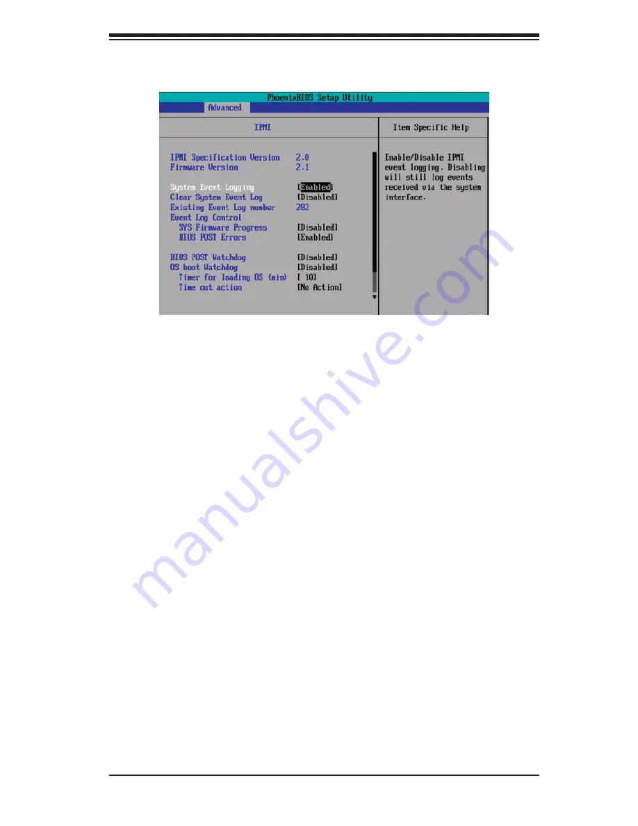
IPMI (Available only when an IPMI card is installed.)

0IP0M0000I Specification Version:

 This item displays the current IPMI 

Version.

Firmware Version: 

This item displays the current Firmware Version.

System Event Logging000

Select Enabled to enable IPMI Event Logging. When this function is set to Disabled, 

the system will continue to log events received via system interface. The options 

are 

Enabled 

and Disabled.

Clear System Event Logging

Enabling this function to force the BIOS to clear the system event logs during the 

next cold boot. The options are Enabled and 

Disabled

.

Existing Event Log Number

This item displays the number of the existing event log.

Event Log Control

System Firmware Progress

Enabling this function to log POST progress. The options are Enabled and 

Disabled

.

BIOS POST Errors

Enabling this function to log POST errors. The options are Enabled and 

Disabled

.

BIOS POST Watch Dog

Set to Enabled to enable POST Watch Dog. The options are Enabled and 

Disabled

.

Содержание SUPERSERVER 6015C-M3

Страница 1: ...SUPER USER S MANUAL Revision 1 0a SUPERSERVER 6015C M3 SUPERSERVER 6015C MT...

Страница 2: ...or the resolution of any such disputes Super Micro s total liability for all claims will not exceed the price paid for the hardware product FCC Statement This equipment has been tested and found to co...

Страница 3: ...chapter provides a checklist of the main components included with the server system and describes the main features of the Super X7DCL 3 X7DCL i serverboard and the SC813MTQ 520C chassis Chapter 2 Se...

Страница 4: ...moving processors or main memory and when reconfiguring the serverboard Chapter 6 Advanced Chassis Setup Refer to Chapter 6 for detailed information on the SC813MTQ 520C 1U rackmount server chassis Yo...

Страница 5: ...v Preface Notes...

Страница 6: ...O Panel 1 5 Cooling System 1 5 1 4 Contacting Supermicro 1 6 Chapter 2 Server Installation 2 1 Overview 2 1 2 2 Unpacking the System 2 1 2 3 Preparing for Setup 2 1 Choosing a Setup Location 2 1 Rack...

Страница 7: ...Chapter 4 System Safety 4 2 General Safety Precautions 4 2 4 3 ESD Precautions 4 3 4 4 Operating Precautions 4 4 Chapter 5 Advanced Serverboard Setup 5 1 Handling the Serverboard 5 1 Precautions 5 1...

Страница 8: ...Serial Bus USB 5 15 Wake On LAN 5 15 Wake On Ring 5 15 Power Supply Fail Detect 5 16 Alarm Reset 5 16 PWR I2 C 5 16 BPI2 C 5 16 Serial Ports 5 17 SGPIO Headers 5 17 Power LED Speaker 5 17 Keylock 5 1...

Страница 9: ...g the Front Bezel 6 3 SAS SATA Drive Installation 6 4 Accessing the Drive Bays 6 4 DVD ROM Drive Installation 6 6 6 5 Power Supply 6 7 Power Supply Failure 6 7 Replacing the Power Supply 6 7 Chapter 7...

Страница 10: ...SUPERSERVER 6015C M3 6015C MT User s Manual x...

Страница 11: ...Two CPU heatsinks SNK P0017 One 1 slim DVD ROM drive DVM PNSC 824 B SAS SATA Accessories Four 4 SAS SATA hard drive carriers CSE PT 39 B One 1 internal SAS SATA backplane BPN SAS 815TQ One 1 SAS SATA...

Страница 12: ...board SAS 6015C M3 An onboard LSI 1068E SAS controller in integrated into the X7DCL 3 The hot swappable SAS drives are connected to a backplane that provides power bus termination and configuration se...

Страница 13: ...ard IDE controller supports Ultra ATA 100 hard drives or ATAPI devices Onboard I O backpanel ports include one COM port a VGA port two USB ports PS 2 mouse and keyboard ports and two Gigabit LAN NIC p...

Страница 14: ...O W83627HG VGA PCI 33MHz VGA CONN KB MS ISL6312A 2 3 4 5 ISL6312A PROCESSOR 1 1067 1333 MT S 1067 1333 MT S USB 0 1 2 3 4 PCIE X4 0 2 0 1 DDR2 667 PORT 6 7 PCI EXP x8 1 2 1 1 DDR2 667 IDE IT8213F DMI...

Страница 15: ...rmation LEDs indicate power on network activity hard disk drive activ ity and system overheat conditions The control panel also includes a main power button and a system reset button The front of the...

Страница 16: ...Address Super Micro Computer B V Het Sterrenbeeld 28 5215 ML s Hertogenbosch The Netherlands Tel 31 0 73 6400390 Fax 31 0 73 6416525 Email sales supermicro nl General Information support supermicro n...

Страница 17: ...ide on a suitable location for the rack unit that will hold the SuperServer 6015C M3 6015C MT It should be situated in a clean dust free area that is well ventilated Avoid areas where heat electrical...

Страница 18: ...er Always make sure the rack is stable before extending a component from the rack You should extend only one component at a time extending two or more si multaneously may cause the rack to become unst...

Страница 19: ...ing Equipment should be mounted into a rack so that a hazardous condition does not arise due to uneven mechanical loading Circuit Overloading Consideration should be given to the connection of the equ...

Страница 20: ...ide just behind the preinstalled front inner rails Note that these two rails are left right specific Installing the Rear Inner Rails First locate the right rear inner rail the rail that will be used o...

Страница 21: ...sition the chassis rail guides at the desired location in the rack keeping the sliding rail guide facing the inside of the rack Screw the assembly securely to the rack using the brackets provided Atta...

Страница 22: ...ll the server into the rack Do this by lining up the rear of the chassis rails with the front of the rack rails Slide the chassis rails into the rack rails keeping the pressure even on both sides you...

Страница 23: ...the chassis four total First determine how far the server will extend out the front of the rack Larger chassis should be positioned to balance the weight between front and back If a bezel is included...

Страница 24: ...from you until it stops Lift the top cover from the chassis to gain full access to the inside of the 3 server Checking the Components and Setup You may have one or more processors already installed in...

Страница 25: ...Chapter 2 Server Installation 2 9 Figure 2 4 Accessing the Inside of the SuperServer 6015C M3 6015C MT...

Страница 26: ...pending upon your system s configuration your system may have one 3 or more SAS SATA drives already installed If you need to install SAS SATA drives please refer to the appropriate section in Chapter...

Страница 27: ...n off switch on the power supply This chapter explains the meanings of all LED indicators and the appropriate response you may need to take 3 2 Control Panel Buttons There are two push buttons located...

Страница 28: ...ndition which may be caused by cables obstructing the airflow in the system or the ambient room temperature being too warm Check the routing of the cables and make sure all fans are present and operat...

Страница 29: ...drive failure If one of the SAS drives fail you should be notified by your system management software Please refer to Chapter 6 for instructions on replacing failed SAS drives SATA Drives 6015C MT Eac...

Страница 30: ...3 4 SUPERSERVER 6015C M3 6015C MT User s Manual Notes...

Страница 31: ...g power you should first power down the system with the operating system first and then unplug the power cords of all the power supply units in the system When working around exposed electrical circui...

Страница 32: ...one replaced Contact technical support for details and support 4 2 General Safety Precautions Follow these rules to ensure general safety Keep the area around the 6015C M3 6015C MT clean and free of c...

Страница 33: ...uipment from ESD Use a grounded wrist strap designed to prevent static discharge Keep all components and printed circuit boards PCBs in their antistatic bags until ready for use Touch a grounded metal...

Страница 34: ...the chassis cover is in place when the 6015C M3 6015C MT is operating to assure proper cooling Out of warranty damage to the 6015C M3 6015C MT system can occur if this practice is not strictly followe...

Страница 35: ...t to handle them very carefully see previous chapter To prevent the X7DCL 3 X7DCL i serverboard from bending keep one hand under the center of the board to support it when handling The following measu...

Страница 36: ...can then lift the top cover from the chassis to gain full access to the 2 inside of the server If already installed in a rack you must first release the retention screws that secure the unit to the ra...

Страница 37: ...originally after reconnecting them make sure the red wires connect to the pin 1 locations The following data cables with their locations noted should be connected See the layout on page 5 9 for connec...

Страница 38: ...t Blue USB 0 1 Ports Figure 5 2 I O Ports NMI x Key Vcc 5V Stby Vcc 3V Vcc 3V Stby Vcc 3V Stby Vcc 3V Reserved Reset Button Power Button Ground x Key Power On LED IDE SATA LED NIC1 LED NIC2 LED OH Fan...

Страница 39: ...Intel certified multi directional heatsinks and fans When purchasing a Xeon CPU or when receiving a serverboard with a CPU 2 pre installed make sure that the CPU plastic cap is in place and none of th...

Страница 40: ...ally or vertically and do not rub the CPU against any surface or any of the contacts which may damage the CPU and or contacts 7 With the CPU in the socket inspect the four corners of the CPU to make s...

Страница 41: ...Screw in two diagonal screws i e the 1 and the 2 screws until just snug Do not fully tighten the screws or you may damage the CPU 4 Add the two remaining screws then finish the installation by fully...

Страница 42: ...See the Memory Installation table Below Pay attention to the notches along the bottom of the module to prevent insert 2 ing it incorrectly Gently 3 press down on the DIMM module until it snaps into pl...

Страница 43: ...iser card 2 Secure the add on card with the locking tab 3 Possible System Memory Allocation Availability System Device Size Physical Memory Remaining Available 4 GB Total System Memory Firmware Hub fl...

Страница 44: ...ual Figure 5 4 X7DCL 3 X7DCL i Layout SAS components are included on the X7DCL 3 only Jumpers not indicated are for test purposes only A square contact pad indicates the location of pin 1 5 8 Serverbo...

Страница 45: ...COM1 Serial Port Header Fan 1 6 Chassis CPU Fan Headers Floppy Floppy Disk Drive Connector iButton iButton optional for RAID 5 Support IDE IDE Drive Compact Flash Card Connector JAR1 Alarm Rest Heade...

Страница 46: ...power connector You must also connect the 8 pin JPW1 proces sor power connector to your power supply Refer to the table below right for the PW2 12V connector Required Connection ATX Power 24 pin Conne...

Страница 47: ...S Serial ATA and IDE See the table on the right for pin definitions OH Fan Fail LED Pin Definitions JF1 Pin Definition 7 Vcc 8 Ground NIC1 LED Pin Definitions JF1 Pin Definition 11 Vcc 12 Ground NIC2...

Страница 48: ...r IO panel The mouse port is above the keyboard port See the table on the right for pin definitions NMI Button The non maskable interrupt button header is located on pins 19 and 20 of JF1 Refer to the...

Страница 49: ...e USB access cables not included See the tables on the right for pin definitions Wake On LAN Pin Definitions JWOL Pin Definition 1 5V Standby 2 Ground 3 Wake up USB Ports Pin Definitions USB0 1 Pin De...

Страница 50: ...ions Pin Definition 1 Clock 2 Data 3 Power Fail 4 Ground 5 3 3V BPI2 C This connector provides backpanel access for I2 C which may be used to monitor the status of the power supply fan and system temp...

Страница 51: ...IO1 and 3 SGPIO2 X7DCL 3 only are used for SAS activity See the table on the right for pin definitions SGPIO Headers Pin Definitions T SGPIO1 T SGPIO2 3 SGPIO1 3 SGPIO2 Pin Definition Pin Definition 1...

Страница 52: ...S which will also clear any passwords Instead of pins this jumper consists of contact pads to prevent accidentally clearing the contents of CMOS To clear CMOS First power down the system and unplug th...

Страница 53: ...ee the table on the right for jumper settings The default setting is enabled LAN1 2 Enable Disable Jumper Settings JPL1 2 Jumper Setting Definition Pins 1 2 Enabled Pins 2 3 Disabled SAS Enable Disabl...

Страница 54: ...ystem Refer to the table on the right for system status System Status LED Indicator LED4 LED Color Definition Green Power On system normal Red PWR on PWR problem s occur s or 3rd PS not properly insta...

Страница 55: ...ld be used to take advantage of the speed this new technology offers The blue connector connects to the onboard IDE connector interface and the other connector s to your hard drive s Consult the docum...

Страница 56: ...st Data 7 4 Host Data 8 5 Host Data 6 6 Host Data 9 7 Host Data 5 8 Host Data 10 9 Host Data 4 10 Host Data 11 11 Host Data 3 12 Host Data 12 13 Host Data 2 14 Host Data 13 15 Host Data 1 16 Host Data...

Страница 57: ...ctly to enable the SAS con troller SAS Port Pin Definitions SAS0 SAS7 Pin Definition 1 Ground 2 TXP 3 TXN 4 Ground 5 RXN 6 RXP 7 Ground SATA Ports There are no jumpers to en able the SATA ports which...

Страница 58: ...5 24 SUPERSERVER 6015C M3 6015C MT User s Manual Notes...

Страница 59: ...very carefully The following measures are generally sufficient to protect your equipment from ESD discharge Precautions Use a grounded wrist strap designed to prevent static discharge Touch a grounded...

Страница 60: ...ators These wires have been bundled together in a ribbon cable to sim plify the connection Connect the cable from JF1 on the serverboard to the control panel PCB printed circuit board Make sure the re...

Страница 61: ...fan fails you will need to have it replaced with the same type Contact your vendor or Supermicro for information on replacement fans 6 4 Drive Bay Installation Removal Removing the Front Bezel If your...

Страница 62: ...he chassis Proceed to the DVD ROM Drive Installation section in this chapter for instructions Note that only a slim DVD ROM drive will fit into the 6015C M3 6015C MT SAS SATA Drive Installation The SA...

Страница 63: ...Chapter 6 Advanced Chassis Setup 6 5 Figure 6 4 Mounting a Drive in a Carrier Figure 6 5 Removing a SAS SATA Drive from the Server...

Страница 64: ...ime push the cover away from you until it stops You can then lift the top cover from the chassis to gain full access to the inside of the server Note You must power down the system before installing o...

Страница 65: ...op chassis cover by releasing the retention screws that secure 2 the module to the rack then grasp the two handles on either side and pull the module straight out until it locks you will hear a click...

Страница 66: ...User s Manual Reconnect the power cord 4 Replace the chassis top cover and push the module back into the rack 5 Finish by turning the power switch on the power supply on and then depress 6 the power...

Страница 67: ...off a backup battery pro vides power to the CMOS Logic enabling it to retain system parameters Each time the computer is powered on the computer is configured with the values stored in the CMOS Logic...

Страница 68: ...By pressing Delete immediately after turning the system on or 1 When the message shown below appears briefly at the bottom of the screen 2 during the POST Power On Self Test press the Delete key to a...

Страница 69: ...e Using the arrow keys highlight the month day and year fields and enter the correct data Press the Enter key to save the data BIOS Date This field displays the date when this version of BIOS was buil...

Страница 70: ...een for detailed options of these items Set the correct configurations accordingly The items included in the sub menu are Type This option allows the user to select the type of IDE hard drive The opti...

Страница 71: ...ormat Multi Sector Transfers This item allows the user to specify the number of sectors per block to be used in multi sector transfer The options are Disabled 4 Sectors 8 Sectors and 16 Sectors LBA Mo...

Страница 72: ...is set to Enhanced the following items will display Serial ATA SATA RAID Enable Select Enable to enable Serial ATA RAID Functions For the Windows OS environment use the RAID driver if this feature is...

Страница 73: ...by skipping certain tests after the computer is turned on The settings are Enabled and Disabled If Disabled the POST routine will run at normal speed QuietBoot Mode This setting allows you to Enable...

Страница 74: ...ptions are Enabled and Disabled Summary Screen This setting allows you to Enable or Disable the summary screen which displays the system configuration during bootup XMemory Cache Cache System BIOS Are...

Страница 75: ...tect to prevent data from being written into the base memory area of Block 512 640K Select Write Back to allow the CPU to write data back directly from the buffer without writing data to the System Me...

Страница 76: ...can When enabled this setting will initialize the device expansion ROM The options are Enabled and Disabled Enable Master This setting allows you to enable the selected device as the PCI bus master Th...

Страница 77: ...is setting specifies the ECC Error conditions that an SERR is to be asserted The options are None Single Bit Multiple Bit and Both 4GB PCI Hole Granularity This feature allows you to select the granul...

Страница 78: ...ed by the CPU Set to Enabled to enable Enhanced Halt State to lower CPU voltage frequency to prevent overheat The options are Enabled and Disabled Note please refer to Intel s web site for detailed in...

Страница 79: ...allows you to assign control of serial port A The options are Enabled user defined Disabled and Auto BIOS or OS controlled Base I O Address This setting allows you to select the base I O address for...

Страница 80: ...nt Log Validity This is a display to inform you of the event log validity It is not a setting Event Log Capacity This is a display to inform you of the event log capacity It is not a setting View DMI...

Страница 81: ...2K 38 4K 57 6K and 115 2K Console Type This item allows you to choose the console redirection type The options are VT100 VT100 8bit PC ANSI 7bit PC ANSI VT100 and VT UTF8 Flow Control This item allows...

Страница 82: ...nd vice versa If the option is set to 3 pin fan the fan speed is controlled by voltage If the option is set to 4 pin the fan speed will be controlled by Pulse Width Modulation PWM Select 3 pin if your...

Страница 83: ...options are Enabled and Disabled Clear System Event Logging Enabling this function to force the BIOS to clear the system event logs during the next cold boot The options are Enabled and Disabled Exist...

Страница 84: ...nore this option when OS Boot Watch Dog is set to Disabled Time Out Option This feature allows the user to determine what action to take in an event of a system boot failure The options are No Action...

Страница 85: ...Chapter 7 BIOS 7 19 XRealtime Sensor Data This feature display information from motherboard sensors such as temperatures fan speeds and voltages of various components...

Страница 86: ...upervisor password has been entered for the system User Password Is This indicates if a user password has been entered for the system Clear means such a password has not been used and Set means a user...

Страница 87: ...ove are bootable devices listed in the sequence of boot order as specified The boot functions for the devices included in the candidate list above are currently disabled Use a key or a key to move the...

Страница 88: ...p utility Exit Discarding Changes Highlight this item and hit Enter to exit the BIOS Setup utility without saving any changes you may have made Load Setup Defaults Highlight this item and hit Enter to...

Страница 89: ...ed Keyboard controller failed test May require replacing keyboard controller Keyboard locked Unlock key switch Unlock the system to proceed Monitor type does not match CMOS Run SETUP Monitor type not...

Страница 90: ...rs to run Setup If the failure was caused by incorrect values and they are not corrected the next boot will likely fail On systems with control of wait states improper Setup settings can also terminat...

Страница 91: ...Allocation Error for device Run ISA or EISA Configuration Utility to resolve resource conflict for the specified device CD ROM Drive CD ROM Drive identified Entering SETUP Starting Setup program Fail...

Страница 92: ...fixed disk and drive A are properly identified Parity Check 1 nnnn Parity error found in the system bus BIOS attempts to locate the address and display it on the screen If it cannot locate the addres...

Страница 93: ...t in the LCT Run an I2O Configuration Utility e g the SAC utility System BIOS shadowed System BIOS copied to shadow RAM UMB upper limit segment address nnnn Displays the address nnnn of the upper limi...

Страница 94: ...A 6 SUPERSERVER 6015C M3 6015C MT User s Manual Notes...

Страница 95: ...error in the top left corner of the screen The following is a list of codes that may be written to port 80h Appendix B BIOS POST Codes POST Code Description 01h IPMI Initialization 02h Verify Real Mod...

Страница 96: ...down 38h Shadow system BIOS ROM 3Ah Auto size cache 3Ch Advanced configuration of chipset registers 3Dh Load alternate registers with CMOS values 41h Initialize extended memory for RomPilot optional...

Страница 97: ...nd IRQs optional 81h Late POST device initialization 82h Detect and install external RS232 ports 83h Configure non MCD IDE controllers 84h Detect and install external parallel ports 85h Initialize PC...

Страница 98: ...nate QuietBoot optional B6h Check password optional B7h Initialize ACPI BIOS and PPM Structures B9h Prepare Boot BAh Initialize SMBIOS BCh Clear parity checkers BDh Display MultiBoot menu BEh Clear sc...

Страница 99: ...rrupt vectors F1h Initialize Run Time Clock F2h Initialize video F3h Initialize System Management Manager F4h Output one beep F5h Clear Huge Segment F6h Boot to Mini DOS F7h Boot to Full DOS If the BI...

Страница 100: ...B 6 SUPERSERVER 6015C M3 6015C MT User s Manual Notes...

Страница 101: ...he Windows operating system and other software drivers The necessary drivers are all included on the Super Micro CD that came packaged with your system Note the current version of the ICH9R SATA RAID...

Страница 102: ...A RAID Functions Native Mode 1 Press the Del key during system bootup to enter the BIOS Setup Utility Note If it is the first time powering on the system we recommend that you load the Optimized Defau...

Страница 103: ...n appears after Power On Self Test b When you see the above screen press the Ctrl and the I keys simultane ously The main menu of the SATA RAID Utility will appear Note All graphics and screen shots s...

Страница 104: ...a drive and press Space to select it A triangle appears to confirm the selection of the drive f Use the Up Arrow Down Arrow keys to select the stripe size ranging from 4 KB to 128 KB for the RAID 0 a...

Страница 105: ...elect the previous menu c When the RAID Level item is highlighted press the Up Arrow Down Arrow keys to select RAID 1 Mirror and hit Enter d When the Capacity item is highlighted enter your RAID volum...

Страница 106: ...Arrow Down Arrow keys to select the stripe size from 4 KB to 128 KB for your RAID 10 and hit Enter The default setting is 64 KB Note For a server please use a lower stripe size and for a multimedia sy...

Страница 107: ...ight a drive and press Space to select it A triangle appears to confirm the selection of the drive f Use the Up Arrow Down Arrow keys to select the stripe size ranging from 4 KB to 128 KB for the RAID...

Страница 108: ...isk drives when deleting a RAID set a From the main menu select item2 Delete RAID Volume and press Enter b Use the Up Arrow Down Arrow keys to select the RAID set you want to delete and press Del A Wa...

Страница 109: ...u select item3 Reset Disks to Non RAID and press En ter The following screen will appear b Use the Up Arrow Down Arrow keys to highlight the RAID set drive to reset and press Space to select c Press E...

Страница 110: ...e Enter key Choose the Intel R ICH9R SATA RAID Controller from the list indicated in the 5 XP 2000 2003 Setup Screen and press the Enter key Press the Enter key to continue the installation process If...

Страница 111: ...item on the list The X7DCL 3 supports SAS RAID features To configure the LSI SAS 2 HostRAID please refer to the LSI folder for the LSI SAS HostRAID Utility and documentation The LSI folder is included...

Страница 112: ...or III displays crucial system information such as CPU temperatures system voltages and fan status See the Figure below for a display of the Supero Doctor III interface Note 1 Both default username an...

Страница 113: ...ontrol Note SD III Software can be downloaded from our Web site at ftp ftp supermicro com utility Supero_Doctor_III You can also download SDIII User s Guide at http www supermicro com PRODUCT Manuals...

Страница 114: ...D 4 SUPERSERVER 6015C M3 6015C MT User s Manual Notes...

Страница 115: ...o 48 GB of registered ECC DDR2 667 533 SDRAM Note interleaved memory requires DIMMs to be installed in pairs refer to Section 5 6 for details SAS Controller 6015C M3 LSI 1068E SAS Serial Attached SCSI...

Страница 116: ...ing Four 4 high performance 4 cm fans System Input Requirements AC Input Voltage 100 240V AC auto range Rated Input Current 7A 3A max Rated Input Frequency 50 to 60 Hz Power Supply Rated Output Power...

Страница 117: ...N 61000 4 11 Safety EN 60950 IEC 60950 Compliant UL Listed USA CUL Listed Canada TUV Certified Germany CE Marking Europe California Best Management Practices Regulations for Perchlorate Materials This...

Страница 118: ...ure to perform be reasonably expected to result in significant injury or loss of life or catastrophic property damage Accordingly Supermicro dis claims any and all liability and should buyer use or se...

Отзывы: