background image

2-22


PDSG4/PDSGE User's Manual

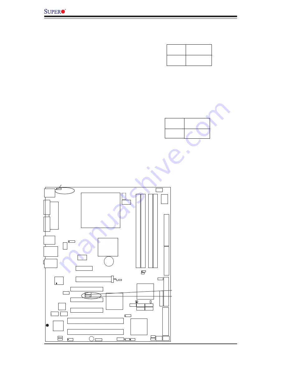
SMBus to PCI/PCI-Exp. Slots

Jumpers JP1, JP2  allow you to connect


PCI/PCI-E slots to the System Management 

Bus

.

   The default setting is "Open"  to dis-

able the connection.  See the table on the 

right for jumper settings. 

Jumper

Position

closed

*Open

Definition

Enabled

Disabled

 SMBus to PCI/PCI-Exp

(*Default)

Keyboard Wake-Up 

The JPWAKE  jumper is used together 

with the Keyboard Wake-Up function in 

BIOS. Enable both the jumper and the 

BIOS setting to allow the system to be 

woken up when the user  hits a key on the 

keyboard.  See the table on the right for 

jumper settings.  Your power supply must 

meet  ATX specifi cation 2.01 or higher and 

supply 720 mA of standby power to use 

this feature.

Jumper

Position

1-2
2-3

Definition

Enabled

Disabled

 Keyboard Wake-Up

Jumper Settings

JP1

JP2

 Slot 1 PCI-X100 MH z  ZCR

Slot 3 PCI 32 bit 33MHz

Slot 5 PCI 32 bit 33MHz

S

UPER   PDSG4 

REV 1.

011

®

Pentium Dural Core

CPU

LGA 775

JPWAKE

KB/MS

Printer

COM1

USB

3/4/5/6

USB1/2

& LAN

Fan5

Clock

955X

Glenwood

(North Bridge)

 Slot 6 PCI-E  x16

LAN CTRL

J P L 1

CD1

Aux1

Slot 7 PCI-E x1

SCSI

J L 1

SATA1

Fan4

Buzzer

D 1 0

IDE

24-Pin ATX PWR

Fan2

ICH7R

DIMM#1A (Blue)

DIMM#2A (Black)

DIMM#1B (Blue)

DIMM#2B (Black)

Audio

WOL

J B T 1

J F 1

JPW1

(South Bridge)

J 5

J 7

J6

J 1

J2

J4

PNG

JPW2

8-pin PWR

COM2

J 1 0

J 9

FDD

J 1 8

SATA3

LE2

JPUSB1

Fan1

Battery

Slot 4 PCI 32 bit 33MHz

LE1

J 1 1

JLED

JPA1

Fan3

FP Aud

JPA2

J P 1

J P 2

Slot 2 PCI-X 100 MHz

JPUSB2

P X H

SCSI Channel

FP CTRL

L E 3

FPUSB7/8

J 1 2

J 1 7

SI/O

PCIE-MR1

SATA0 SATA2

JWOR

J W D

BIOS

AC'97

SPKR

(The Green Slot)

J 8

JPF

JPWAKE

Содержание PDSG4

Страница 1: ...PDSG4 PDSGE USER S MANUAL Revision 1 1...

Страница 2: ...OR DATA Any disputes arising between manufacturer and customer shall be governed by the laws of Santa Clara County in the State of California USA The State of California County of Santa Clara shall be...

Страница 3: ...the features speci cations and performance of the PDSG4 PDSGE mainboard and provides detailed information about the chipset Chapter 2 provides hardware installation instructions Read this chapter whe...

Страница 4: ...m 1 10 1 2 Chipset Overview 1 11 1 3 PC Health Monitoring 1 12 1 4 Power Con guration Settings 1 12 1 5 Power Supply 1 13 1 6 Super I O 1 14 Chapter 2 Installation 2 1 Static Sensitive Devices 2 1 2 2...

Страница 5: ...2 22 Keyboard Wake Up 2 22 SCSI Enable 2 23 SCSI Termination Enable 2 23 2 8 LED Indicators 2 24 G LAN LEDs 2 24 2 9 Parallel Port Floppy Hard Drive and Audio Connections 2 25 Parallel Port Connector...

Страница 6: ...4 4 4 2 Advanced Chipset Control 4 6 4 4 3 I O Device Con guration 4 7 4 4 4 PnP Con guration 4 8 4 4 5 Hardware Monitors 4 9 4 4 6 Processor Clock Options 4 10 4 4 7 DMI Event Log 4 11 4 4 8 Console...

Страница 7: ...and performance Please check that the following items have all been included with your motherboard If anything listed here is damaged or missing contact your retailer All Included in the Retail Box O...

Страница 8: ...SuperMicro Computer B V Het Sterrenbeeld 28 5215 ML s Hertogenbosch The Netherlands Tel 31 0 73 6400390 Fax 31 0 73 6416525 Email sales supermicro nl General Information support supermicro nl Technic...

Страница 9: ...ge An Important Note to the User All images and layouts shown in this manual are based upon the latest PCB Revision available at the time of publishing The motherboard you ve received may or may not l...

Страница 10: ...ot are for the PDSG4 only Figure 1 3A The PDSG4 Motherboard Layout not drawn to scale Slot 1 PCI X100 MH z ZCR Slot 3 PCI 32 bit 33MHz Slot 5 PCI 32 bit 33MHz S UPER PDSG4 REV 1 011 PentiumDuralCore C...

Страница 11: ...iary Audio Input Header CD In CD1 Audio CD Input Header COM1 J2 COM2 J1 COM Port 1 Port 2 Connectors DIMM 1A 2A 1B 2B Memory DIMM Slots 1 through 4 Fans 1 5 Fan1 CPU Fan Fan2 3 4 5 Chassis Fan Headers...

Страница 12: ...B1 Fan1 LE1 J11 JLED Fan3 FP Aud JP1 JP2 Slot 2PCI X133 MHz JPUSB2 PXH FP CTRL L E 3 FPUSB7 8 J12 J17 SI O PCIE MR1 S A T A 0 S A T A 2 JWOR JWD BIOS AC 97 SPKR J8 JPF Battery Important Notes to the U...

Страница 13: ...COM2 J1 COM Port 1 Port 2 Connectors DIMM 1A 2A 1B 2B Memory DIMM Slots 1 through 4 Fans 1 5 Fan1 CPU Fan Fan2 3 4 5 Chassis Fan Headers FP Audio J8 Front Panel Audio Header See Chapter 2 FP Control J...

Страница 14: ...ture in the BIOS Enable the HT feature in the BIOS under Advanced Setting before install ing a supported OS Note visit www Intel com for CPU support and driver updates OS Licensing Support Intel Dual...

Страница 15: ...hannel Adaptec 7901 Single channel Ultra 320 SCSI PDSG4 only Adaptec SCSI RAID 20105 Supermicro AOC LPZCR supported PDSG4 Only Intel ICH7R Controller supports up to 4 Serial ATA SATA 3Gb s Hard Disks...

Страница 16: ...s of each motherboard GLENWOOD SLOTS LGA775_PROCESSOR ICH 7R USB PORT_0 7 FWH LPC I O MS KB FDD SER 1 SER 2 PRN PRI_IDE VRM 10 1 CTRL ADDR DATA UDMA 100 LPC PCI_32_BUS DDR2_667 533 VRM V10 1 DMI 3_PCI...

Страница 17: ...ct between the MCH and the ICH7R The ICH7R supports up four Serial ATA ports eight USB 2 0 ports and two IDE devices In addition the ICH7R offers the Intel Matrix Storage Technology which provides var...

Страница 18: ...ser enables the CPU overheat warning function in the BIOS This allows the user to de ne an overheat temperature When this temperature reaches the threshold the CPU thermal trip feature will be activat...

Страница 19: ...pin header on a Network Interface Card NIC that has WOL capability Wake On LAN must be enabled in BIOS Note that Wake On LAN can only be used with an ATX 2 01 or above compliant power supply 1 5 Powe...

Страница 20: ...44 M or 2 88 M disk drives and data transfer rates of 250 Kb s 500 Kb s or 1 Mb s It also provides two high speed 16550 compatible serial communication ports UARTs Each UART includes a 16 byte send re...

Страница 21: ...its edges only do not touch its components peripheral chips memory modules or gold contacts When handling chips or modules avoid touching their pins Put the motherboard and peripherals back into their...

Страница 22: ...GA 775 heatsink and fan comes with a push pin design and no tool is needed for installation 4 Make sure to install the motherboard into the chassis before you install the CPU heatsink and fan 5 When p...

Страница 23: ...ce or against any pins of the socket to avoid damage to the CPU or the socket 7 With the CPU inside the socket inspect the four corners of the CPU to make sure that the CPU is properly installed 8 Use...

Страница 24: ...sink 7 Align the four heatsink fasteners with the mounting holes on the mother board Gently push the pairs of diago nal fasteners 1 2 and 3 4 into the mounting holes until you hear a click Note Make s...

Страница 25: ...lease take all necessary precautionary measures to prevent damage done to these compo nents when installing the motherboard into the chassis 8 Repeat Step 6 to insert all four heatsink fasteners into...

Страница 26: ...Edition 64 Bit Windows Server 2003 Standard Enterprise XP x64 Edition Note 2 You may install a maximum of 2GB DIMMs on each slot however only DDR 2 533 2GB density modules are available for this con g...

Страница 27: ...Pink Mic Blue Line In Green Line Out See Notes COM2 Port Front Control Panel JF1 contains header pins for various buttons and indicators that are normally located on a control panel at the front of th...

Страница 28: ...2 JP1 JP2 Slot 2 PCI X 100 MHz JPUSB2 PXH SCSI Channel FP CTRL L E 3 FPUSB7 8 J12 J17 SI O PCIE MR1 S A T A 0 S A T A 2 JWOR JWD BIOS AC 97 SPKR The Green Slot J8 JPF 2 6 Connecting Cables Note the gr...

Страница 29: ...ATX PWR Fan2 ICH7R DIMM 1A Blue DIMM 2A Black DIMM 1B Blue DIMM 2B Black Audio WOL J B T 1 JF1 JPW1 South Bridge J5 J7 J 6 J1 J2 J4 PNG JPW2 8 pinPWR COM2 J10 J9 FDD J18 S A T A 3 LE2 JPUSB1 Fan1 Bat...

Страница 30: ...idge J5 J7 J 6 J1 J2 J4 PNG JPW2 8 pinPWR COM2 J10 J9 FDD J18 S A T A 3 LE2 JPUSB1 Fan1 Battery Slot 4 PCI 32 bit 33MHz LE1 J11 JLED JPA1 Fan3 FP Aud JPA2 JP1 JP2 Slot 2 PCI X 100 MHz JPUSB2 PXH SCSI...

Страница 31: ...nnel FP CTRL L E 3 FPUSB7 8 J12 J17 SI O PCIE MR1 S A T A 0 S A T A 2 JWOR JWD BIOS AC 97 SPKR The Green Slot J8 JPF Power Button OH Fan Fail LED 1 NIC1 LED Reset Button 2 x HDD LED Power LED Reset Pw...

Страница 32: ...inform you of a chassis intrusion Pin Number 1 2 Definition Intrusion Input Ground Chassis Intrusion Pin Definitions JL1 Slot 1 PCI X100 MH z ZCR Slot 3 PCI 32 bit 33MHz Slot 5 PCI 32 bit 33MHz S UPER...

Страница 33: ...ry Audio Header A 4 pin CD header CD1 and an Auxiliary header Aux1 are located on the motherboard These headers allow you to use the onboard sound for audio CD playback Connect the audio cable from yo...

Страница 34: ...t 4 PCI 32 bit 33MHz LE1 J11 JLED JPA1 Fan3 FP Aud JPA2 JP1 JP2 Slot 2 PCI X 100 MHz JPUSB2 PXH SCSI Channel FP CTRL L E 3 FPUSB7 8 J12 J17 SI O PCIE MR1 S A T A 0 S A T A 2 JWOR JWD BIOS AC 97 SPKR T...

Страница 35: ...pinPWR COM2 J10 J9 FDD J18 S A T A 3 LE2 JPUSB1 Fan1 Battery Slot 4 PCI 32 bit 33MHz LE1 J11 JLED JPA1 Fan3 FP Aud JPA2 JP1 JP2 Slot 2 PCI X 100 MHz JPUSB2 PXH SCSI Channel FP CTRL L E 3 FPUSB7 8 J12...

Страница 36: ...PUSB2 PXH SCSI Channel FP CTRL L E 3 FPUSB7 8 J12 J17 SI O PCIE MR1 S A T A 0 S A T A 2 JWOR JWD BIOS AC 97 SPKR The Green Slot J8 JPF Fan Headers The PDSG4 PDSGE has five fan headers Fan1 to Fan5 Not...

Страница 37: ...JPUSB2 PXH SCSI Channel FP CTRL L E 3 FPUSB7 8 J12 J17 SI O PCIE MR1 S A T A 0 S A T A 2 JWOR JWD BIOS AC 97 SPKR The Green Slot J8 JPF Wake On Ring The Wake On Ring header is desig nated JWOR This f...

Страница 38: ...capable 6 FP_RETURN_R Right channel audio signal return from front panel when headphones unplugged 7 NC NC NC no connection 8 Key No pin 9 FP_OUT_L Left channel audio signal to front panel headphone...

Страница 39: ...FP Aud JPA2 JP1 JP2 Slot 2 PCI X 100 MHz JPUSB2 PXH SCSI Channel FP CTRL L E 3 FPUSB7 8 J12 J17 SI O PCIE MR1 S A T A 0 S A T A 2 JWOR JWD BIOS AC 97 SPKR The Green Slot J8 JPF 2 7 Jumper Settings Exp...

Страница 40: ...g Enable JWD controls Watch Dog a system monitor that takes action when a software application freezes the system Close Pins 1 2 to reset the system if a program hangs Close Pins 2 3 to generate a non...

Страница 41: ...32 bit 33MHz Slot 5 PCI 32 bit 33MHz S UPER PDSG4 REV 1 011 PentiumDuralCore CPU LGA 775 JPWAKE KB MS Printer COM1 USB 3 4 5 6 USB1 2 LAN Fan5 Clock 955X Glenwood North Bridge Slot6PCI E x16 LAN CTRL...

Страница 42: ...standby power to use this feature Jumper Position 1 2 2 3 Definition Enabled Disabled Keyboard Wake Up Jumper Settings JP1 JP2 Slot 1 PCI X100 MH z ZCR Slot 3 PCI 32 bit 33MHz Slot 5 PCI 32 bit 33MHz...

Страница 43: ...unction properly please do not change the default setting See the table on the right for jumper settings Slot 1 PCI X100 MH z ZCR Slot 3 PCI 32 bit 33MHz Slot 5 PCI 32 bit 33MHz S UPER PDSG4 REV 1 011...

Страница 44: ...D JPA1 Fan3 FP Aud JPA2 JP1 JP2 Slot 2 PCI X 100 MHz JPUSB2 PXH SCSI Channel FP CTRL L E 3 FPUSB7 8 J12 J17 SI O PCIE MR1 S A T A 0 S A T A 2 JWOR JWD BIOS AC 97 SPKR The Green Slot J8 JPF LAN Port GL...

Страница 45: ...21 BUSY 23 PE 25 SLCT Pin Number Function 2 Auto Feed 4 Error 6 Init 8 SLCT IN 10 GND 12 GND 14 GND 16 GND 18 GND 20 GND 22 GND 24 GND 26 NC Parallel Printer Port Pin Definitions Parallel Port Slot 1...

Страница 46: ...Slot 1 PCI X100 MH z ZCR Slot 3 PCI 32 bit 33MHz Slot 5 PCI 32 bit 33MHz S UPER PDSG4 REV 1 011 PentiumDuralCore CPU LGA 775 JPWAKE KB MS Printer COM1 USB 3 4 5 6 USB1 2 LAN Fan5 Clock 955X Glenwood N...

Страница 47: ...S16 34 GND 36 Addr 2 38 Chip Select 1 40 GND IDE Connector Pin Definitions Slot 1 PCI X100 MH z ZCR Slot 3 PCI 32 bit 33MHz Slot 5 PCI 32 bit 33MHz S UPER PDSG4 REV 1 011 PentiumDuralCore CPU LGA 775...

Страница 48: ...955X Glenwood North Bridge Slot6PCI E x16 LAN CTRL JPL1 CD1 Aux1 Slot7PCI Ex1 SCSI JL1 S A T A 1 Fan4 Buzzer D10 IDE 24 Pin ATX PWR Fan2 ICH7R DIMM 1A Blue DIMM 2A Black DIMM 1B Blue DIMM 2B Black Au...

Страница 49: ...move all add on cards 6 Install a CPU and heatsink Be sure that it is fully seated and then connect the chassis speaker and the power LED to the motherboard Check all jumper settings as well 7 It is i...

Страница 50: ...battery on your motherboard may be old Check to verify that it still supplies 3VDC If it does not replace it with a new one 3 If the above steps do not x the Setup Con guration problem contact your ve...

Страница 51: ...eaved or non interleaved SDRAM See Section 2 4 for details on installing memory Question How do I update my BIOS Answer It is recommended that you do not upgrade your BIOS if you are experi encing no...

Страница 52: ...ction of the BIOS setup Question I installed my microphone correctly but I can t record any sound What should I do Answer Go to Start Programs Accessories Entertainment and then Volume Control Under t...

Страница 53: ...ly covers normal consumer use and does not cover damages in curred in shipping or from failure due to the alteration misuse abuse or improper maintenance of products During the warranty period contact...

Страница 54: ...3 6 PDSG4 PDSGE User s Manual Notes...

Страница 55: ...wer to the BIOS Flash chip enabling it to retain the system parameters Each time the computer is powered on the computer is then con gured with the values stored in the BIOS ROM by the system BIOS whi...

Страница 56: ...ed in one of two ways 1 By pressing Del immediately after turning the system on or 2 When the following message appears brie y at the bottom of the screen during the POST Power On Self Test press the...

Страница 57: ...the parameters of the IDE Channels 0 1 Master Slave slots Hit Enter to activate the following sub menu screen for detailed options Be sure to set the correct con gurations accordingly The items inclu...

Страница 58: ...that inform you how much of each type of memory is recognized as being present in the system 4 4 Advanced BIOS Setup Choose Advanced BIOS Setup from the Award BIOS main menu with the Left Right arrow...

Страница 59: ...ivate the BIOS Support for Advanced Con guration and Power Interface features The settings are Enabled or Disabled ACPI Suspend Type If enabled the option allows the user to select the ACPI Suspend ty...

Страница 60: ...r the system The options are IDE RAID and APCI On Chip Serial ATA Select Disabled to disable the SATA Controller Select Auto to allow the BIOS to make arrangements automatically Select Combined Mode t...

Страница 61: ...roller The options are Disabled and Enabled Onboard Serial Port1 Onboard Serial Port2 This setting allows the user to set the address and the corresponding IRQ for the Serial Port1 and Serial Port 2 T...

Страница 62: ...and Play compatible devices If you choose Auto you cannot select the IRQ DMA and memory base address elds because the BIOS automatically assigns them The options are Auto ESCD and Manual PCI Optional...

Страница 63: ...es allows you to set the Chipset warning temperature If the chipset temperature reaches the pre set threshold an alarm will be activated and a warning message will be displayed on the screen The optio...

Страница 64: ...o any programs that support it you must have OS support also The settings are Disabled and Enabled Set to Enabled for the Windows XP and Linux 2 4x operating systems Disable this feature for operating...

Страница 65: ...as Read Highlight this item and press Enter to mark the DMI events as read 4 4 8 Console Redirection Console Redirection This setting allows you to Enable or Disable the function of Console Redirectio...

Страница 66: ...ervisor Password in the dialogue box to set or to change the Supervisor Password Set User Password When the item Set User Password is highlighted on the above screen press the Enter key When prompted...

Страница 67: ...ces First Boot Device Second Boot Device Third Boot Device This item allows the user to set the rst boot up device The options are Removable Hard Disk CD ROM Legacy LAN IBA GE Slot21 and Disabled The...

Страница 68: ...without saving any changes you may have made Your system should then continue with the boot up procedure Load Fail Safe Defaults Highlight this item and hit Enter to load the default settings for all...

Страница 69: ...The following is a list of such BIOS messages A 1 BIOS POST Beep Codes Beeps Error Messages 1 repetitive long beep Memory Modules Errors 1 long beep 2 short beeps VGA Errors A 2 LE1 LE2 Indicators Sta...

Страница 70: ...A 2 PDSG4 PDSGE User s Manual Notes...

Страница 71: ...address 1000 0 02h Reserved 03h Initial Superio_Early_Init switch 04h Reserved 05h 1 Blank out screen 2 Clear CMOS error ag 06h Reserved 07h 1 Clear 8042 interface 2 Initialize 8042 self test 08h 1 T...

Страница 72: ...ebook platform 20h Reserved 21h HPM initialization notebook platform 22h Reserved 23h 1 Check validity of RTC value e g a value of 5Ah is an invalid value for RTC minute 2 Load CMOS settings into BIOS...

Страница 73: ...O chips 34h Reserved 35h Reserved 36h Reserved 37h Reserved 38h Reserved 39h Reserved 3Ah Reserved 3Bh Reserved 3Ch Test 8254 3Dh Reserved 3Eh Test 8259 interrupt mask bits for channel 1 3Fh Reserved...

Страница 74: ...rs multi processor platform 56h Reserved 57h 1 Display PnP logo 2 Early ISA PnP initialization Assign CSN to every ISA PnP device 58h Reserved 59h Initialize the combined Trend Anti Virus code 5Ah Res...

Страница 75: ...go is supported If errors occur report errors and wait for keys If no errors occur or F1 key is pressed to continue Clear EPA or customization logo 80h Reserved 81h Reserved 82h 1 Call chipset power m...

Страница 76: ...4 Power management nal initialization 5 Clear screen and display memory table 6 Program K6 write allocation 7 Program P6 class write combining 95h 1 Program daylight saving 2 Update keyboard LED and...

Страница 77: ...ort Windows XP 2000 2003 Operating Systems Serial ATA SATA Serial ATA SATA is a physical storage interface that uses a single cable with a minimum of four wires to create a point to point connection b...

Страница 78: ...ode 1 Press the Del key during system bootup to enter the BIOS Setup Utility Note If it is the rst time powering on the system we recommend you load the Optimized Default Settings If you have already...

Страница 79: ...rs after Power On Self Test b When you see the above screen press the Ctrl and the I keys simultane ously to have the main menu of the SATA RAID Utility appear Note All graphics and screen shots shown...

Страница 80: ...d press Space to select it A triangle appears to con rm the selection of the drive f Use the Up Arrow Down Arrow keys to selet the stripe size ranging from 4 KB to 128 KB for the RAID 0 array and hit...

Страница 81: ...t the previous menu c When RAID Level item is highlighted press the Up Arrow Down Arrow keys to select RAID 1 Mirror and hit Enter d When the Capacity item is highlighted enter your RAID volume capaci...

Страница 82: ...Arrow keys to select the stripe size from 4 KB to 128 KB for your RAID 10 and hit Enter The default setting is 6 4KB Note For a server please use a lower stripe size and for a multimedia system use a...

Страница 83: ...a drive and press Space to select it A triangle appears to con rm the selection of the drive f Use the Up Arrow Down Arrow keys to select the stripe size ranging from 4 KB to 128 KB for the RAID 5 arr...

Страница 84: ...s when deleting a RAID set a From the main menu select item2 Delete RAID Volume and press Enter b Use the Up Arrow Down Arrow keys to select the RAID set you want to delete and press Del A Warning mes...

Страница 85: ...ID set drive A Warning message displays d Press Y to reset the drive or type N to go back to the main menu Exiting the Intel Matrix Storage Manager Utility a From the main menu select item4 Exit and p...

Страница 86: ...ontroller from the list indicated in the XP 2000 2003 Setup Screen and press the Enter key f Press the Enter key to continue the installation process If you need to specify any additional devices to b...

Страница 87: ...op to the bottom one at a time After installing each item you must re boot the system before moving on to the next item on the list The bottom icon with a CD on it allows you to view the entire conten...

Страница 88: ...e installation in the welcoming window 15 Intel ICH5R Serial ATA RAID Introduction The InstallShield Wizard will begin automatically for installation showed as following Click on the Next button to pr...

Страница 89: ...marked Yes on the screen and the following screen will appear Intel ICH5R Serial ATA RAID Introduction 16 After reading the license agreement in the following window click Y es button to continue Sel...

Страница 90: ...00 2003 Operating System is installed please read the Readme text les for the instructions to use the SATA RAID Utility in the Windows XP 2000 2003 OS environment 17 Intel ICH5R Serial ATA RAID Introd...

Страница 91: ...h your motherboard Note for the Windows 2003 OS please refer to Page C 14 Driver Tool Installation Display Screen Note Click the icons showing a hand writing on the paper to view the readme les for ea...

Страница 92: ...ges and fan status See the Figure below for a display of the Supero Doctor III interface Note 1 The default user name and password are ADMIN Note 2 In the Windows OS environment the Supero Doctor III...

Страница 93: ...ed from our Website at ftp ftp supermicro com utility Supero_Doctor_III You can also download SDIII User s Guide at http www supermicro com PRODUCT Manuals SDIII UserGuide pdf For Linux we will still...

Страница 94: ...C 18 PDSG4 PDSGE User s Manual Notes...

Отзывы: