


Chapter 2: Installation
2-13
I
2
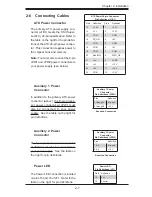
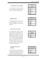
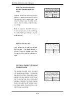
C Header for Power Supply
The I
2
C header at J16 may be used
to monitor the power supply. See the
table on the right for pin defi nitions.
I
2
C Header for Power
Supply
Pin Defi nitions (J16)
Pin# Defi nition
1
Clock
2
Data
3
PWR Fail
4
Gnd
5
+3.3V
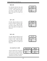
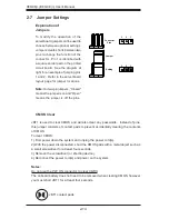
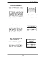
SMBus Header
The JSMB header is provided for
System Management Bus connec-
tion. See the table on the right for pin
defi nitions.
SMBus Header
Pin Defi nitions (JSMB)
Pin# Defi nition
1
Data
2
Gnd
3
Clock
4
NC
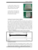
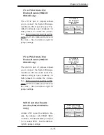
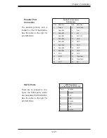
Additional Fan Headers
Four additional fan headers, desig-
nated nFAN1 through nFAN4, are
included on the serverboard. On the
H8QC8/H8QCE, nFAN1 and nFAN2
should be connected to the heatsinks
on the CK804 and 8132 (chipset)
chips. On the H8QC8+/H8QCE+,
nFAN3 and nFAN4 should be con-
nected to the heatsinks that are used
with the air shroud. See the table on
the right for pin defi nitions.
Additional Fan Header
Pin Defi nitions
(nFAN1-4)
Pin# Defi nition
1
12V
2
Ground
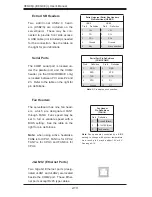
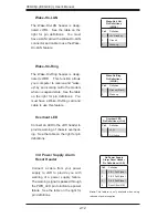
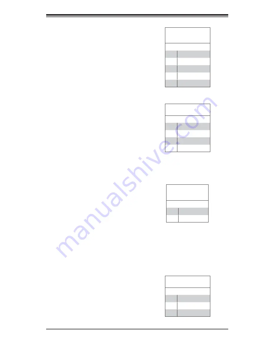
Compact Flash Power
Headers
JWF1 and JWF2 are power headers for
compact fl ash devices, which can be
connected to the IDE ports. See the
table on the right for pin defi nitions.
DOC Power Header
Pin Defi nitions (JWF1)
Pin# Defi nition
1
+5V
2
Ground
3
Signal
Содержание H8QC8+
Страница 1: ...H8QC8 H8QC8 H8QCE H8QCE USER S MANUAL Revision 1 0c ...
Страница 47: ...Chapter 2 Installation 2 25 Figure 2 5 Driver Installation Screen ...
Страница 48: ...2 26 H8QC8 H8QCE User s Manual Notes ...
Страница 72: ...A 2 H8QC8 H8QCE User s Manual Notes ...
Страница 80: ...B 8 H8QC8 H8QCE User s Manual Notes ...