background image

1-8

C2SEA/C2SEE User’s Manual

C2SEA/C2SEE 

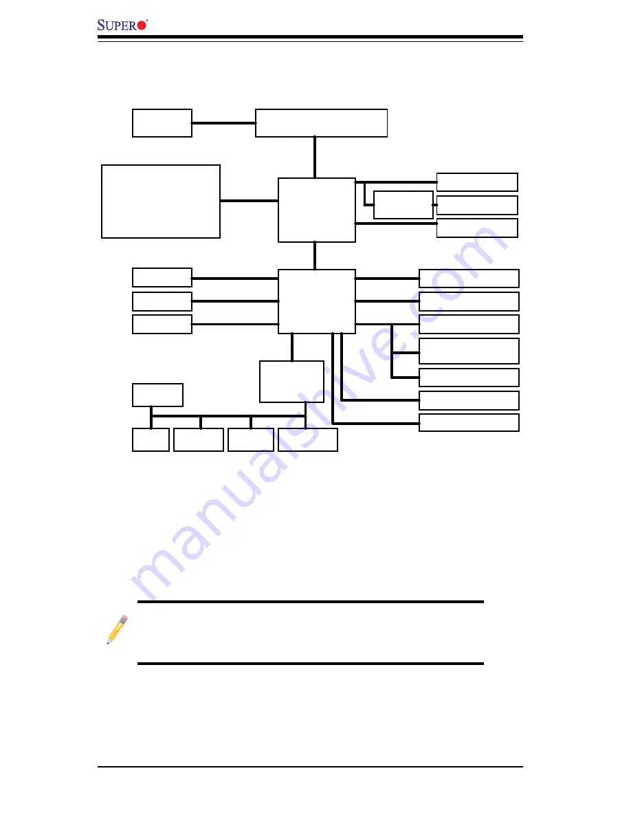
System Block Diagram

Note

: This is a general block diagram and may not exactly represent 

the features on your motherboard. See the following pages for the 

actual specifi cations of each motherboard. 

Block Diagram

LGA775 Processor

LPC I/O

PCI_32_BUS

DDR3:
1333/1066/800

DMI

ITE 8213F IDE

DIMM1A, CH 1

MCH

DIMM1B, CH 1

PCI-E x1 Slot

PCIE_x1

W83627DHG

FSB: 1333/1066/800

HDMI(C2SEA)

PCIE_x16

Realtek RTL8111C

VRM 11.1

PCI-E x16

SATAII /300

SATA x6

USB x 12

USB2.0

PCI 32 x4 (C2SEE)

TI TSB43AB22A

SPI

MS.

KB.

Floppy

COM1

Parallel

FAN x5

PCIE_X1

PCIE_x4

PCI-E x4

Realtek ALC888

HDA

SPI EEPROM

CRT

G45(C2SEA)
G43(C2SEE)

MUX &

Level Shift

ICH10

PCI 32 x2 (C2SEA)

MEMORY

DIMM

DIMM2A, CH 2

DIMM2B, CH 2

DIMM1A, CH 1

DIMM2A, CH 2

C2SEA

C2SEE

Содержание C2SEA

Страница 1: ...C2SEA C2SEE USER S MANUAL Revision 1 0b...

Страница 2: ...SUCH HARDWARE SOFTWARE OR DATA Any disputes arising between manufacturer and customer shall be governed by the laws of Santa Clara County in the State of California USA The State of California County...

Страница 3: ...d to be installed and serviced by a professional technician Manual Organization Chapter 1 describes features specifications and detailed information about the motherboard and the chipset Chapter 2 pro...

Страница 4: ...s Super Micro Computer B V Het Sterrenbeeld 28 5215 ML s Hertogenbosch The Netherlands Tel 31 0 73 6400390 Fax 31 0 73 6416525 Email sales supermicro nl General Information support supermicro nl Techn...

Страница 5: ...Preface Notes v...

Страница 6: ...10 1 4 PC Health Monitoring 1 10 1 5 ACPI Features 1 10 1 6 Power Supply 1 11 1 7 Versatile Media Capabilities 1 12 1 8 Super I O 1 12 Chapter 2 Installation 2 1 Static Sensitive Devices 2 1 2 2 Moth...

Страница 7: ...S PDIF_Out Connector 2 22 HDMI Connector 2 22 1394_1 1394_2 Connections 2 23 Power LED 2 23 2 7 Jumper Settings 2 24 Explanation of Jumpers 2 24 GLAN Enable Disable 2 24 Watch Dog Enable 2 25 IEEE 139...

Страница 8: ...s 3 3 3 4 Returning Merchandise for Service 3 5 Chapter 4 BIOS 4 1 Introduction 4 1 4 2 Main BIOS Setup 4 2 4 3 Advanced Setup 4 4 4 4 Security Setup 4 18 4 5 Boot Settings 4 19 4 6 Exit 4 20 Appendic...

Страница 9: ...est standards in quality and performance Please check that the following items have all been included with your motherboard If anything listed here is damaged or missing contact your retailer All the...

Страница 10: ...rd Image Note All pictures and drawings shown in this manual were based upon the latest PCB Revision available at the time of publishing of the manual The motherboard you have received may or may not...

Страница 11: ...PCI 33MHz DIMM2A DIMM1B DIMM1A USB7 JF1 USB2 3 4 5 SPDIF_Out J13 Printer I SATA4 I SATA5 Battery Intel G45 C2SEA G43 C2SEE ICH10 Intel Lan CTRL S I O IDE CTRL Motherboard Layout Important Notes to th...

Страница 12: ...Pins 1 2 Enabled JPUSB1 JPUSB2 8 25 USB 2 5 USB 6 11 Enable Pins 1 2 Disabled JWD 37 Watch Dog Timer Out Pins 1 2 Reset C2SEA C2SEE Quick Reference 9 5 4 3 10 11 8 7 6 S I O 1 2 12 13 14 15 16 18 19 2...

Страница 13: ...r JL1 21 Chassis Intrusion Header JLED 38 Onboard Power LED Indicator JPW1 JPW2 ATX 24 Pin Power and 12V 8 Pin Power Connec tors JOH 36 Overheat LED JWOL 16 Wake on LAN Header JWOR 14 Wake On Ring Hea...

Страница 14: ...e 1 PCI Express x1 Slot7 Two 2 32 bit PCI 33MHz Slot1 Slot2 C2SEA Four 4 32 bit PCI 33MHz Slot1 Slot2 Slot3 and Slot5 C2SEE BIOS 8 Mb Firmware SPI AMI Flash BIOS DMI 2 3 PCI 2 3 ACPI 1 0 2 0 3 0 SMBIO...

Страница 15: ...TE 8213F Controller supports one IDE channel two devices C2SEA only 12 USB Universal Serial Bus 2 0 ports Realtek ALC 888 High Definition Audio HDA codecs supports 10 DAC Chan nels Built in GMCH and o...

Страница 16: ...PCI_32_BUS DDR3 1333 1066 800 DMI ITE 8213F IDE DIMM1A CH 1 MCH DIMM1B CH 1 PCI E x1 Slot PCIE_x1 W83627DHG FSB 1333 1066 800 HDMI C2SEA PCIE_x16 Realtek RTL8111C VRM 11 1 PCI E x16 SATAII 300 SATA x...

Страница 17: ...xpress the DMI or the GMCH configuration space Host initiated memory cycles are decoded to PCI Express DMI or system memory Memory accesses initiated from PCI Express will be snooped on the host bus b...

Страница 18: ...res ACPI stands for Advanced Configuration and Power Interface The ACPI specifica tion defines a flexible and abstract hardware interface that provides a standard to integrate power management feature...

Страница 19: ...AN controller can also support WOL without any connection to the WOL header The 3 pin WOL header is to be used with a LAN add on card only Note Wake On LAN requires an ATX 2 01 or above compliant powe...

Страница 20: ...on and protection across multiple partitions This feature is available when a processor that supports the virtualization of platforms is installed on the motherboard 1 8 Super I O The disk drive adapt...

Страница 21: ...not touch its components peripheral chips memory modules or gold contacts When handling chips or modules avoid touching their pins Put the motherboard and peripherals back into their antistatic bags...

Страница 22: ...installing the motherboard to the chassis Tools Needed 1 Philip Screwdriver 2 Pan head 6 screws 9 pcs Installation Instructions 1 Locate the mounting holes on the motherboard Refer to the layout on t...

Страница 23: ...ly make sure that you use only Intel certified multi directional heatsink and fan 4 Make sure to install the motherboard into the chassis before you install the CPU heatsink and fan 5 When receiving a...

Страница 24: ...ket 7 With the CPU inside the socket inspect the four corners of the CPU to make sure that the CPU is properly installed 8 Use your thumb to gently push the load lever down to the lever lock 9 If the...

Страница 25: ...ccur if the protective film is not removed from the heatsink 5 Apply the proper amount of thermal grease on the CPU Note if your heatsink came with a thermal pad please ignore this step 6 If necessary...

Страница 26: ...tsink fan wires to the CPU Fan connector 1 Unplug the power cord from the power supply 2 Disconnect the heatsink fan wires from the CPU fan header 3 Use your finger tips to gently press on the fastene...

Страница 27: ...DIMMs Populating DIMM1A DIMM2A and or DIMM1B DIMM2B with memory modules of the same size and of the same type will result in dual channel two way interleaved memory which is faster than the single cha...

Страница 28: ...y System Device Size Physical Memory Remaining Available 4 GB Total System Memory Firmware Hub flash memory System BIOS 1 MB 3 99 Local APIC 4 KB 3 99 Area Reserved for the chipset 2 MB 3 99 I O APIC...

Страница 29: ...ors IO Ports Back Panel I O Port Locations and Definitions Back Panel Connectors 1 Keyboard Purple 2 PS 2 Mouse Green 3 VGA Blue 4 HDMI C2SEA only 5 S PDIF_Out 6 USB Port 2 7 USB Port 3 8 USB Port 4 9...

Страница 30: ...trol Panel JF1 contains header pins for various buttons and indicators that are normally located on a control panel at the front of the chassis These connectors are designed specifi cally for use with...

Страница 31: ...G43 C2SEE ICH10 Intel Lan CTRL S I O IDE CTRL Power Button OH Fan Fail LED 1 NIC1 LED Reset Button 2 HDD LED Power LED LED_Anode LED_Anode LED_Anode LED_Anode Ground Ground X X LED_Anode 15 16 X Powe...

Страница 32: ...Fan Fail LED 1 NIC1 LED Reset Button 2 HDD LED Power LED LED_Anode LED_Anode LED_Anode LED_Anode Ground Ground X X LED_Anode 15 16 X NIC1 LED Indicators The NIC Network Interface Control ler LED conn...

Страница 33: ...n 1 Signal 2 3V Standby Reset Button The Reset Button connection is located on pins 3 and 4 of JF1 Attach it to a hardware reset switch on the computer case Refer to the table on the right for pin def...

Страница 34: ...G43 C2SEE ICH10 Intel Lan CTRL S I O IDE CTRL 2 6 Connecting Cables ATX Auxiliary Power Connectors A 24 pin main power connector is located at JPW1 and a 8 pin power connector is located at JPW2 on th...

Страница 35: ...thernet port is located above USB Ports 0 1 on the IO back plane This GLAN port accepts RJ45 type cables GLAN1 JL1 JI2C1 JI2C2 JOH JPUSB1 JPI1 JWD JPL1 JPAC JLED JPD1 COM1 JPW1 Floopy JPW2 JWOL DIMM1...

Страница 36: ...ut Printer I SATA4 I SATA5 Battery Intel G45 C2SEA G43 C2SEE ICH10 Intel Lan CTRL S I O IDE CTRL Chassis Intrusion A Chassis Intrusion header is located at JL1 on the motherboard Attach an appropriate...

Страница 37: ...O IDE CTRL Fan Headers The C2SEA C2SEE has five chassis fan headers Fan 1 to Fan 5 Fan 1 is the CPU Fan Fan 2 to Fan 5 are system chassis fans Note Pins 1 3 of a 4 pin fan headers are backward compat...

Страница 38: ...I SATA4 I SATA5 Battery Intel G45 C2SEA G43 C2SEE ICH10 Intel Lan CTRL S I O IDE CTRL ATX PS 2 Keyboard and PS 2 Mouse Ports The ATX PS 2 keyboard and the PS 2 mouse are located on the backplane See...

Страница 39: ...nter I SATA4 I SATA5 Battery Intel G45 C2SEA G43 C2SEE ICH10 Intel Lan CTRL S I O IDE CTRL A JWOR B JWOL Wake On Ring The Wake On Ring header is des ignated JWOR This function allows your computer to...

Страница 40: ...inter I SATA4 I SATA5 Battery Intel G45 C2SEA G43 C2SEE ICH10 Intel Lan CTRL S I O IDE CTRL A High Definition Audio A Grey Side Surround Black Back Surround Orange CEN LFE Pink Mic In Green Front Blue...

Страница 41: ...a 4 pin CD header is located at CD1 on the motherboard These headers allow you to use the onboard sound for audio CD playback Con nect an audio cable from your CD drive to the header that fits your ca...

Страница 42: ...erface support to the onboard audio and video connections See the table below for pin definitions HDMI Pin Definitions Pin Defin Pin Defin 1 TMDS Data2 2 GND 3 TMDS Data2 4 TMDS Data1 5 GND 6 TMDS Dat...

Страница 43: ...n2 LAN1 JPUSB2 DIMM2B DIMM4 DIMM3 USB 10 11 USB 8 9 USB6 1394_2 Slot7 PCI E x1 Slot6 PCI E Gen2 x16 Slot3 PCI 33MHz HD AUDIO JWOR CPU CPU Fan FP Audio 1394_1 CMOS CLEAR C2SEA C2SEE IDE VGA HDMI USB 0...

Страница 44: ...G43 C2SEE ICH10 Intel Lan CTRL S I O IDE CTRL 2 7 Jumper Settings Explanation of Jumpers Tomodifytheoperationofthemotherboard jumpers can be used to choose between optional settings Jumpers create sho...

Страница 45: ...e Watch Dog Enable Disable Watch Dog is a system monitor that can re boot the system when a software application hangs Close pins 1 2 to reset the system if an application hangs Close pins 2 3 to gene...

Страница 46: ...CTRL A JI2 C1 B JI2 C2 C JBT1 PCI PCI E Slots to SMB Speeds Jumpers JI2 C1 JI2 C2 allow you to connect PCI PCI Exp Slots to the System Manage ment Bus The default setting is open to disable the conne...

Страница 47: ...on x16 KB Mouse SPI BIOS Slot2 PCI 33MHz DIMM2A DIMM1B DIMM1A USB7 JF1 USB2 3 4 5 SPDIF_Out Printer I SATA4 I SATA5 Battery Intel G45 C2SEA G43 C2SEE ICH10 Intel Lan CTRL S I O IDE CTRL IDE Enable Dis...

Страница 48: ...a key on a USB keyboard or by clicking the USB mouse of your system The JPUSB jumpers are used together with the USB Wake Up feature in the BIOS Enable both the jumpers and the BIOS setting to allow t...

Страница 49: ...ATA1 I SATA0 Slot1 PCI 33MHz Slot5 PCI 33MHZ Slot4 PCI E x4 on x16 KB Mouse SPI BIOS Slot2 PCI 33MHz DIMM2A DIMM1B DIMM1A USB7 JF1 USB2 3 4 5 SPDIF_Out Printer I SATA4 I SATA5 Battery Intel G45 C2SEA...

Страница 50: ...B2 3 4 5 SPDIF_Out Printer I SATA4 I SATA5 Battery Intel G45 C2SEA G43 C2SEE ICH10 Intel Lan CTRL S I O IDE CTRL GLAN LED Indicators There is a Gigabit LAN port LAN1 on the motherboard This Gigabit Et...

Страница 51: ...ot1 PCI 33MHz Slot5 PCI 33MHZ Slot4 PCI E x4 on x16 KB Mouse SPI BIOS Slot2 PCI 33MHz DIMM2A DIMM1B DIMM1A USB7 JF1 USB2 3 4 5 SPDIF_Out Printer I SATA4 I SATA5 Battery Intel G45 C2SEA G43 C2SEE ICH10...

Страница 52: ...ter I SATA4 I SATA5 Battery Intel G45 C2SEA G43 C2SEE ICH10 Intel Lan CTRL S I O IDE CTRL Parallel Port Connector The parallel printer connector is located at J13 on the motherboard See the table on t...

Страница 53: ...O IDE CTRL IDE Connector C2SEAOnly There is one IDE Connector on the C2SEA This connection supports two IDE devices Be sure to close Pin 1 and Pin 2 of JPD1 to enable the IDE connector before using i...

Страница 54: ...2 34 C2SEA C2SEE User s Manual Notes...

Страница 55: ...l ribbon wire cables from the motherboard including those for 2 the keyboard and mouse Remove all add on cards 3 Install a CPU and heatsink making sure it is fully seated and connect the 4 chassis spe...

Страница 56: ...ing unbuffered DDR3 memory see the next page Also it 2 is recommended that you use the same memory speed for all DIMMs in the system See Section 2 4 for memory limitations Check for bad DIMM modules o...

Страница 57: ...be flashed some cannot be flashed It depends on the modifications to the boot block code 3 If you still cannot resolve the problem include the following information when contacting Supermicro for tec...

Страница 58: ...stem will automatically reboot If you choose the exe file please run the exe file under Windows to create the BIOS flash floppy disk Insert the floppy disk into the system you wish to flash the BIOS T...

Страница 59: ...ect the blue connector to the onboard IDE header and the other connector s to your hard drive s Consult the documentation that came with your disk drive for details on actual jumper locations and sett...

Страница 60: ...3 6 C2SEA C2SEE User s Manual Notes...

Страница 61: ...an area reserved for a text message When an option is selected in the left frame it is highlighted in white Often a text message will accompany it Note the AMI BIOS has default text messages built in...

Страница 62: ...screen by selecting the Main tab on the top of the screen The Main BIOS Setup screen is shown below System Overview The following BIOS information will be displayed System Time System Date Use this o...

Страница 63: ...r When you select this option the AMI BIOS will automatically display the status of processors as shown below Speed Count System Memory This option allows the AMI BIOS to display the status of memory...

Страница 64: ...Enabled to allow the computer system to display the OEM logo Wait for F1 If Error Select Enable to allow the system to wait for the user to press F1 when an error occurs The options are Enabled and Di...

Страница 65: ...r more than 5 minutes The options are Enabled and Disabled USB Device Wake Up Select Enable to wake up the system via a USB device when the system is in S3 Standby or S4 Hibernate State The options ar...

Страница 66: ...if an invalid ratio is entered the AMI BIOS will restore the setting to the previous state CPU VID This feature allows the user to set VID for the processor When this feature is set to Enabled C1E and...

Страница 67: ...Processing Available when supported by the CPU Set to Enabled to use a processor s Second Core and beyond Please refer to Intel s web site for more information The options are Disabled and Enabled In...

Страница 68: ...ed for use of PCI devices If set to 15 MB 16MB the reserved memory will be placed in the location around 15 MB 16 MB The options are Disabled and 15 MB 16 MB Initiate Graphics Adapter Use this feature...

Страница 69: ...eo applications DVMT Fixed Memory This option allows the user to set the amount of memory to be used for the operation of DVMT Fixed Mode The options are 128 MB 256 MB and Maximum DVMT Flat Panel Type...

Страница 70: ...lly protected I O resource sharing across the Intel platforms providing the user with greater reliability security and availability in networking and data sharing The settings are Enabled and Disabled...

Страница 71: ...nd solution for an operating system that does not have EHCI Hand Off support When enabled the EHCI Interface will be changed from the BIOS controlled to the OS controlled The options are Disabled and...

Страница 72: ...be transferred per interrupt if Block Mode is not used Block Mode allows transfers of up to 64 KB per interrupt Select Disabled to allow data to be transferred from and to the device one sector at a...

Страница 73: ...It has a data transfer rate of 25 MBs Select UltraDMA2 to allow the BIOS to use Ultra DMA mode 2 It has a data transfer rate of 33 3 MBs Select UltraDMA3 to allow the BIOS to use Ultra DMA mode 3 It h...

Страница 74: ...f each PCI device installed on a PCI bus Select 64 to set the PCI latency to 64 PCI clock cycles The options are 32 64 96 128 160 192 224 and 248 Allocate IRQ to PCI VGA Select Yes to allow the system...

Страница 75: ...P EPP Parallel Port IRQ This setting allows the to select the IRQ interrupt request for the parallel port The options are IRQ5 and IRQ7 uHardware Health Configuration This feature allows the user to m...

Страница 76: ...n Select Server if your system is used as a Server Select Disabled to disable the fan speed control function and allow the onboard fans to constantly run at the full speed 12V The Options are Disabled...

Страница 77: ...ord has not been used and Set means a user password has been entered for the system Change Supervisor Password Select this option and press Enter to access the submenu and then type in a new Superviso...

Страница 78: ...and Always Setup Ask for password before granting access to the BIOS setup utility only Always Ask for password before granting access to the BIOS setup utility and each time the system boots Boot Sec...

Страница 79: ...e 1st Floppy Drive and Disabled The default settings are the fol lowing 1st Boot Device 1st Floppy Drive 2nd Boot Device SATA uHard Disk Drives This feature allows the user to specify the boot sequenc...

Страница 80: ...it Select this option to quit the BIOS Setup without making any permanent changes to the system configuration and reboot the computer Select Discard Changes and Exit from the Exit menu and press Enter...

Страница 81: ...IOS 4 21 Load Fail Safe Defaults To set this feature select Load Fail Safe Defaults from the Exit menu and press Enter The Fail Safe settings are designed for maximum system stability but not for maxi...

Страница 82: ...4 22 C2SEA C2SEE User s Manual Notes...

Страница 83: ...turer for possible repairs These fatal errors are usually communicated through a series of audible beeps The numbers on the fatal error list on the following page correspond to the num ber of beeps fo...

Страница 84: ...A 2 C2SEA C2SEE User s Manual Notes...

Страница 85: ...u need 4 to specify any additional devices to be installed do it at this time Once all devices are specified press the Enter key to continue with the installation From the Windows XP 2000 2003 Setup s...

Страница 86: ...B 2 C2SEA C2SEE User s Manual Notes...

Страница 87: ...each item you must re boot the system before proceeding with the next item on the list The bottom icon with a CD on it allows you to view the entire contents of the CD Appendix C Software Installatio...

Страница 88: ...splays crucial system information such as CPU temperature system voltages and fan status See the Figure below for a display of the Supero Doctor III interface Note 1 Both default user name and passwor...

Страница 89: ...te Control Note SD III Software Revision 1 0 can be downloaded from our Web site at ftp ftp supermicro com utility Supero_Doctor_III You can also download SDIII User s Guide at http www supermicro com...

Страница 90: ...C 4 C2SEA C2SEE User s Manual Notes...

Страница 91: ...expected to result in significant injury or loss of life or catastrophic property damage Accordingly Supermicro disclaims any and all liability and should buyer use or sell such products for use in su...

Отзывы: