


Chapter 5: Advanced Serverboard Setup
5-7
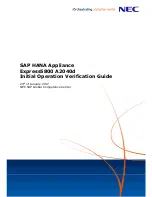
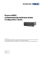
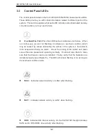
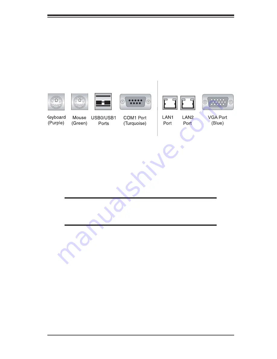
5-4 I/O
Ports
The I/O ports are color coded in conformance with the PC 99 specifi cation. See
Figure 5-2 below for the colors and locations of the various I/O ports.
Figure 5-2. Rear Panel I/O Ports
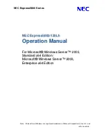
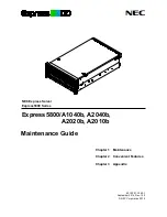
5-5 Installing
Memory
Note:
Check the Supermicro web site for recommended memory modules.
CAUTION
Exercise extreme care when installing or removing DIMM modules
to prevent any possible damage.
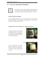
1. Insert the desired number of DIMMs into the memory slots, starting with Bank1
of CPU1. Pay attention to the notch along the bottom of the module to prevent in-
serting the module incorrectly (see Figure 5-3). Note support information below.
2. Gently press down on the memory module until it snaps into place.
Note:
each processor has its own built-in memory controller, so the CPU2 DIMMs
cannot be addressed if only a single CPU is installed. 128 MB, 256 MB, 512 MB, 1
GB and 2 GB memory modules are supported. It is highly recommended that you
remove the power cord from the system before installing or changing any memory
modules. Using DIMMs of the same type and speed is recommended.
Содержание AS1021M-T2R
Страница 1: ...AS1021M T2R USER S MANUAL 1 0a SUPER ...
Страница 5: ...v Preface Notes ...
Страница 10: ...Notes x AS1021M T2R User s Manual ...
Страница 25: ...Chapter 2 Server Installation 2 9 Figure 2 5 Accessing the Inside of the System ...
Страница 30: ...3 4 AS1021M T2R User s Manual Notes ...
Страница 70: ...6 10 AS1021M T2R User s Manual Figure 6 6 Removing Replacing the Power Supply ...
Страница 90: ...A 2 AS1021M T2R User s Manual Notes ...
Страница 98: ...B 8 AS1021M T2R User s Manual Notes ...
Страница 102: ...C 4 AS1021M T2R User s Manual Notes ...