background image

2-4

AS4041M-T2R/4041M-82R User's Manual

2-4  Installing the System into a Rack

This section provides information on installing the system into a rack unit.  Rack 

installation requires the use of the optional rackmount kit.  If the system has already 

been mounted into a rack or if you are using it as a tower, you can skip ahead to 

Sections 2-5 and 2-6.  There are a variety of rack units on the market, which may 

mean the assembly procedure will differ slightly.  The following is a guideline for 

installing the server into a rack with the rack rails provided in the rackmount kit.  

You should also refer to the installation instructions that came with the rack unit 

you are using.     

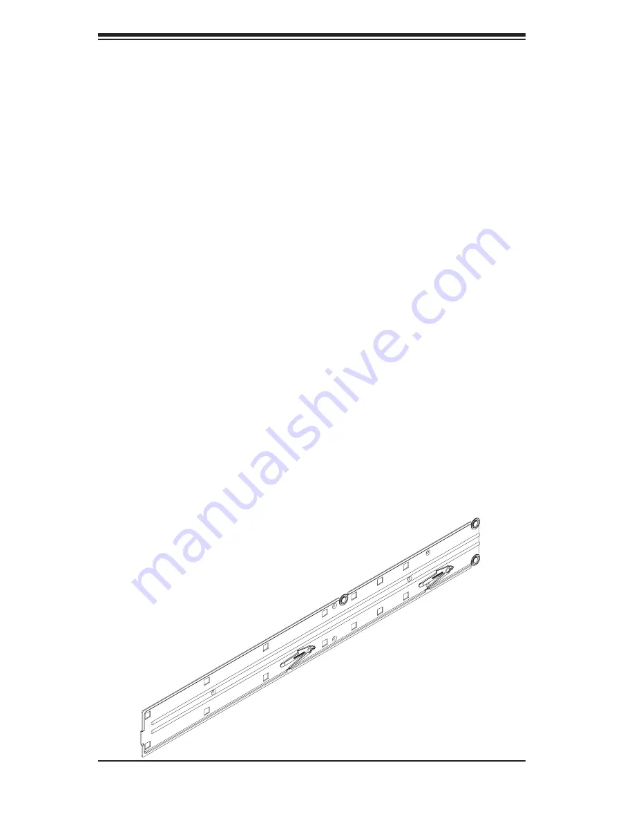
 Identifying the Sections of the Rack Rails

The optional rackmount kit (MCP-290-00001-00) includes two rack rail assemblies.  

Each of these assemblies consist of two sections: an inner fi xed chassis rail that 

secures to the chassis and an outer rack rail that secures directly to the rack itself.  

The inner and outer rails must be detached from each other before installing.   

To remove the inner chassis rail, pull it out as far as possible - you should hear a 

"click" sound as a locking tab emerges from inside the rail assembly and locks the 

inner rail.  Depress the locking tab to pull the inner rail completely out.  Do this for 

both assemblies (one for each side).     

Figure 2-1.  Inner Fixed Chassis Rail

Содержание AS-4041M-82R

Страница 1: ...AS4041M T2R AS4041M 82R USER S MANUAL 1 0 ...

Страница 2: ...PRODUCT OR DOCUMENTATION EVEN IF ADVISED OF THE POSSIBILITY OF SUCH DAMAGES IN PARTICULAR THE VENDOR SHALL NOT HAVE LIABILITY FOR ANY HARDWARE SOFTWARE OR DATA STORED OR USED WITH THE PRODUCT INCLUDING THE COSTS OF REPAIRING REPLACING INTEGRATING INSTALLING OR RECOVERING SUCH HARDWARE SOFTWARE OR DATA Any disputes arising between manufacturer and customer shall be governed by the laws of Santa Cla...

Страница 3: ...ction The first chapter provides a checklist of the main components included with the server system and describes the main features of the H8QME 2 H8QM8 2 serverboard and the SC748TQ R1000 SC748S R1000 chassis which comprise the AS4041M T2R 4041M 82R Chapter 2 Server Installation This chapter describes the steps necessary to install the AS4041M T2R 4041M 82R into a rack and check out the server con...

Страница 4: ... processors or main memory and when reconfiguring the serverboard Chapter 6 Advanced Chassis Setup Refer to Chapter 6 for detailed information on the SC748TQ R1000 SC748S R1000 server chassis You should follow the procedures given in this chapter when install ing removing or reconfiguring SATA SCSI or peripheral drives and when replacing system power supply modules and cooling fans Chapter 7 BIOS Th...

Страница 5: ...v Preface Notes ...

Страница 6: ...Setup 2 1 Choosing a Setup Location 2 2 Rack Precautions 2 2 Server Precautions 2 2 Rack Mounting Considerations 2 3 2 4 Installing the System into a Rack 2 4 2 5 Checking the Serverboard Setup 2 8 2 6 Checking the Drive Bay Setup 2 9 Chapter 3 System Interface 3 1 Overview 3 1 3 2 Control Panel Buttons 3 1 Power 3 1 Reset 3 1 3 3 Control Panel LEDs 3 2 Power 3 2 HDD 3 2 NIC1 3 2 NIC2 3 2 Overheat...

Страница 7: ...mory 5 7 5 6 Adding PCI Cards 5 9 5 7 Serverboard Details 5 10 H8QME 2 H8QM8 2 Layout 5 10 H8QME 2 H8QM8 2 Quick Reference 5 11 5 8 Connector Definitions 5 12 ATX Power Connector 5 12 Processor Power Connectors 5 12 NMI Button 5 12 Power LED 5 13 HDD LED 5 13 NIC1 LED 5 13 NIC2 LED 5 13 Overheat Fan Fail LED 5 13 Power Fail LED 5 14 Reset Button 5 14 Power Button 5 14 Universal Serial Bus USB0 1 5 ...

Страница 8: ...le Disable 5 21 Compact Flash Master Slave 5 21 PCI X Slot Frequency Select 5 22 Watch Dog Enable Disable 5 22 5 10 Onboard Indicators 5 23 JLAN1 JLAN2 LEDs 5 23 Onboard Power LED 5 23 5 11 Floppy IDE Paralllel Port SCSI and SATA Drive Connections 5 24 Floppy Connector 5 24 IDE Connector 5 25 Parallel Port 5 25 SATA Ports 5 26 SCSI Connectors 5 27 5 12 Enabling SATA RAID 5 28 5 13 Installing Softw...

Страница 9: ...ng the Power Supply 6 9 Chapter 7 BIOS 7 1 Introduction 7 1 7 2 Main Menu 7 2 7 3 Advanced Settings Menu 7 2 7 4 Boot Menu 7 16 7 5 Security Menu 7 17 7 6 Exit Menu 7 18 Appendices Appendix A BIOS Error Beep Codes A 1 Appendix B BIOS POST Codes B 1 Appendix C System Specifications C 1 ...

Страница 10: ...Notes x AS4041M T2R 4041M 82R User s Manual ...

Страница 11: ... slim DVD ROM drive DVM PNSC 824 B One 1 front control panel cable CBL 0087 One 1 floppy drive FPD PNSC W1 44MB One 1 floppy cable CBL 0051L Three 3 9 cm hot swap chassis fans FAN 0090 Three 3 8 cm hot swap exhaust fans FAN 0081 One 1 air shroud CSE PT0125 Four 4 passive heatsinks for AMD Socket F CPU SNK P0023P SATA Accessories 4041M T2R only One 1 SATA backplane BPN SAS M35TQ Five 5 SATA data cabl...

Страница 12: ...CP55 SATA controller is integrated into the H8QME 2 H8QM8 2 to provide a six port 3 Gb sec Serial ATA subsystem which is RAID 0 1 0 1 5 and JBOD supported The SATA drives are hot swappable units Note The operating system you use must have RAID support to enable the hot swap capability and RAID function of the Serial ATA drives SCSI Subsystem 4041M 82R The H8QME 2 includes an onboard Adaptec AIC 79...

Страница 13: ...i tors a chassis intrusion header auto switching voltage regulators chassis and CPU overheat sensors virus protection and BIOS rescue 1 3 Server Chassis Features The AS4041M T2R 4041M 82R is a high end scaleable server platform built upon the SC748TQ R1000 SC748S R1000 tower 4U server chassis The following is a general outline of the main features of the SC748TQ R1000 SC748S R1000 chassis System P...

Страница 14: ...uded I O Backplane The SC748TQ R1000 SC748S R1000 is a tower chassis that may also be used in a 4U rackmount configuration Ports on the I O backplane include one COM port a VGA port two USB 2 0 ports PS 2 mouse and keyboard ports a parallel port and two gigabit Ethernet ports Cooling System The SC748TQ R1000 SC748S R1000 chassis has an innovative cooling design that includes three 9 cm hot plug sys...

Страница 15: ...IOS Floppy Kybd Mouse Serial Ports 2 AMD Socket F Type Processor CPU1 AIC 7902W PCI X CH A SCSI Ports 2 LPC IPMI Slot 3 PCI X 133 100 ATI ES 1000 AMD 8132 AMD Socket F Type Processor CPU3 AMD Socket F Type Processor CPU4 16 x 16 HT link 1 GHz Slot 2 PCI X 100 Slot 4 PCI X 133 100 Gb LAN Ports 2 PCI X CH B Slot 5 PCI E x8 Slot 6 PCI E x16 PCI E SIMSO SATA UDMA133 USB 2 0 DIMMC 2A DIMMC 2B DIMMC 1A ...

Страница 16: ...e Address SuperMicro Computer B V Het Sterrenbeeld 28 5215 ML s Hertogenbosch The Netherlands Tel 31 0 73 6400390 Fax 31 0 73 6416525 Email sales supermicro nl General Information support supermicro nl Technical Support rma supermicro nl Customer Support Asia Pacific Address SuperMicro Taiwan 4F No 232 1 Liancheng Rd Chung Ho 235 Taipei County Taiwan R O C Tel 886 2 8226 3990 Fax 886 2 8226 3991 We...

Страница 17: ...skip ahead to Section 2 5 2 2 Unpacking the System You should inspect the box the system was shipped in and note if it was damaged in any way If the server itself shows damage you should file a damage claim with the carrier who delivered it Decide on a suitable location for the SuperServer 4041M T2R 4041M 82R It should be situated in a clean dust free area that is well ventilated Avoid areas where ...

Страница 18: ...be coupled together Always make sure the rack is stable before extending a component from the rack You should extend only one component at a time extending two or more simul taneously may cause the rack to become unstable Server Precautions Review the electrical and general safety precautions in Chapter 4 Determine the placement of each component in the rack before you install the rails Install th...

Страница 19: ...omised Mechanical Loading Equipment should be mounted into a rack so that a hazardous condition does not arise due to uneven mechanical loading Circuit Overloading Consideration should be given to the connection of the equipment to the power supply circuitry and the effect that any possible overloading of circuits might have on overcurrent protection and power supply wiring Appropriate considerati...

Страница 20: ...should also refer to the installation instructions that came with the rack unit you are using Identifying the Sections of the Rack Rails The optional rackmount kit MCP 290 00001 00 includes two rack rail assemblies Each of these assemblies consist of two sections an inner fixed chassis rail that secures to the chassis and an outer rack rail that secures directly to the rack itself The inner and out...

Страница 21: ...ons you just removed along the side of the chassis making sure the screw holes line up Note that these two rails are left right specific Screw the rail securely to the side of the chassis see Figure 2 3 Repeat this procedure for the other rail on the other side of the chassis You will also need to attach the rail brackets when installing into a telco rack Locking Tabs The chassis rails have a locki...

Страница 22: ...tion the fixed rack rail sliding rail guide assemblies at the desired location in the rack keeping the sliding rail guide facing the inside of the rack Screw the assembly securely to the rack using the brackets provided Attach the other assembly to the other side of the rack making both are at the exact same height and with the rail guides facing inward Figure 2 3 Installing the Rails to the Chassi...

Страница 23: ...hese first keeping in mind that they are left right specific marked with L and R Then line up the rear of the chassis rails with the front of the rack rails Slide the chassis rails into the rack rails keeping the pressure even on both sides you may have to depress the locking tabs when inserting When the server has been pushed completely into the rack you should hear the locking tabs click Finish by...

Страница 24: ...the chassis You can then lift the cover from the chassis to gain full access to the inside of the server 2 Check the CPUs processors You may have up to four processors already installed into the serverboard Each processor should have its own heatsink attached See Chapter 5 for instructions on processor installation 3 Check the system memory Your server may have come with system memory already inst...

Страница 25: ...ppy disk drive to the system 4 Check the SATA SCSI disk drives Depending upon your system s configuration your system may have one or more drives already installed If you need to install SATA SCSI drives please refer to Chapter 6 5 Check the airflow Airflow is provided by three hot swap 9 cm chassis fans working in conjunction with an air shroud as well as three 8 cm exhaust fans The system component...

Страница 26: ...2 10 AS4041M T2R 4041M 82R User s Manual Figure 2 5 Accessing the Inside of the System Rack Configuration shown ...

Страница 27: ...specific components There are also two buttons on the chassis control panel 3 2 Control Panel Buttons There are two push button buttons located on the front of the chassis These are in order from left to right a power on off button and a reset button POWER This is the main power button which is used to apply or turn off the main system power Turning off system power with this button removes the mai...

Страница 28: ...On the 4041M T2R 4041M 82R this LED indicates SATA SCSI IDE drive activity when flashing NIC1 Indicates network activity on JLAN1 when flashing NIC2 Indicates network activity on JLAN2 when flashing Overheat Fan Fail When this LED flashes it indicates a fan failure When on continuously it indicates an overheat condition which may be caused by cables obstructing the airflow in the system or the ambient ...

Страница 29: ...backplane enables this LED to blink on and off when that particular drive is being accessed Red The red LED indicates two states When blinking it indicates the drive is rebuilding When solid it indicates a drive failure If a SATA drive fails you should be notified by your system management software Please refer to Chapter 6 for instructions on replacing failed SATA drives 4041M 82R Each SCSI drive ...

Страница 30: ...3 4 AS4041M T2R 4041M 82R User s Manual Notes ...

Страница 31: ...you should first power down the system with the operating system and then unplug the power cords from all the power supply modules in the system When working around exposed electrical circuits another person who is familiar with the power off controls should be nearby to switch off the power if necessary Use only one hand when working with powered on electrical equipment This is to avoid making a c...

Страница 32: ... into a cooling fan Remove any jewelry or metal objects from your body which are excellent metal conductors that can create short circuits and harm you if they come into contact with printed circuit boards or areas where power is present After accessing the inside of the system close the system back up and secure it to the rack unit with the retention screws after ensuring that all connections hav...

Страница 33: ...ll components and printed circuit boards PCBs in their antistatic bags until ready for use Touch a grounded metal object before removing any board from its antistatic bag Do not let components or PCBs come into contact with your clothing which may retain a charge even if you are wearing a wrist strap Handle a board by its edges only do not touch its components peripheral chips memory modules or co...

Страница 34: ...hassis cover is in place when the 4041M T2R 4041M 82R is operating to ensure proper cooling Out of warranty damage to the 4041M T2R 4041M 82R system can occur if this practice is not strictly followed Figure 4 1 Installing the Onboard Battery LITHIUM BATTERY BATTERY HOLDER BATTERY HOLDER LITHIUM BATTERY OR ...

Страница 35: ...te that the size and weight of the serverboard can cause it to bend if handled improperly which may result in damage To prevent the serverboard from bending keep one hand under the center of the board to sup port it when handling The following measures are generally sufficient to protect your equipment from static discharge Precautions Use a grounded wrist strap designed to prevent static discharge...

Страница 36: ...ention modules Exercise extreme caution when handling and installing the proces sor Always connect the power cord last and always remove it be fore adding removing or changing any hardware components 1 Begin by removing the cover plate that protects the CPU Lift the lever on the CPU socket until it points straight up With the lever raised lift open the silver CPU retention plate 2 Use your thumb a...

Страница 37: ...the CPU inserted into the socket inspect the four corners of the CPU to make sure that it is properly in stalled and flush with the socket Then gently lower the silver CPU retention plate into place 5 Carefully press the CPU socket le ver down until it locks into its retention tab For a dual CPU system repeat these steps to install another CPU into the CPU 2 socket and into CPU 2 3 and 4 sockets fo...

Страница 38: ...Once installed these are used to help attach the heatsinks to the CPUs To install align the module with the standoffs of the preinstalled CPU backplate and with the four feet on the module contacting the serverboard Secure the retention module to the backplate with two of the screws provided See Figure 2 1 Repeat for all CPU sockets Note the BKT 0012L is included for use with non proprietary heats...

Страница 39: ... wires connect to the pin 1 locations If you are configuring the system keep the airflow in mind when routing the cables The following data cables with their serverboard connector locations noted should be connected See the serverboard layout diagram in this chapter for connector locations DVD ROM drive cable IDE 1 Control Panel cable JF1 see next page 4041M T2R Serial ATA cables N SATA0 4 4041M 82R...

Страница 40: ... sides of each header All JF1 wires have been bundled into single keyed ribbon cable to simplify their connection The red wire in the ribbon cable plugs into pin 1 of JF1 Connect the other end of the cable to the Control Panel printed circuit board located just behind the system status LEDs in the chassis See the Connector Definitions section in this chapter for details and pin descrip tions of JF1...

Страница 41: ...slot paying attention to the notch along the bottom of the module to prevent inserting the module incorrectly see Figure 5 3 Insert first into the 1A slot s then the 1B slot s then the 2A slot s etc See support information below 2 Gently press down on the memory module until it snaps into place Note Each processor has its own built in memory controller consequently each CPU has a four slot memory b...

Страница 42: ...aved 128 bit memory which is faster than non interleaved 64 bit memory Optimizing memory performance It is better to spread pairs of DIMMs across all memory banks with a CPU installed than to fill up one CPU memory bank while leaving another empty For example if you were to install eight DIMMs in a quad CPU configuration you should install two in the CPU1 DIMM slots slots 1A and 1B two in the CPU2 D...

Страница 43: ...re installing a PCI add on card make sure you power off the system first Begin by removing the top chassis cover Then remove the PCI slot shield for the slot you wish to populate Insert the PCI card into the correct slot pushing down with your thumbs evenly on both sides of the card Screw the top of the card s shield to the backpanel of the chassis to secure it The PCI slot shields protect the serv...

Страница 44: ...CI X ZCR Slot 2 100 MHz PCI X Slot 3 133 100 MHz PCI X Slot 4 133 100 MHz PCI X Slot 5 x8 PCI Express Slot 6 x16 PCI Express HT Connector Floppy JA1 SCSI CH A JPW2 JPW1 J1B1 North Bridge nVidia MCP55 Pro South Bridge AMD 8132 DIMMD 2B DIMMD 1A DIMMD 1B DIMMC 1B DIMMC 1A DIMMC 2B DIMMC 2A DIMMA 2A DIMMA 2B DIMMA 1A DIMMA 1B DIMMB 1B DIMMB 1A DIMMB 2B DIMMB 2A JF2 N SATA5 N SATA4 N SATA2 N SATA0 N S...

Страница 45: ...r FAN 1 9 CPU Chassis Fan Headers Floppy Floppy Disk Drive Connector HT Connector Hyper Tranport Slot IDE 1 IDE Drive Compact Flash Card Connector J1B1 24 Pin ATX Power Connector J3P 3rd Power Supply Fail Detect J4 Parallel Printer Port JA1 JA2 U320 SCSI Channel A B Connector JAR 3rd Power Supply Alarm Reset Header JF1 Front Panel Connector JF2 Onboard Speaker Keylock Power LED JL1 Chassis Intrusi...

Страница 46: ... 10 12V 23 5V 11 12V 24 COM 12 3 3V Processor Power Connector In addition to the primary ATX power connector above the 8 pin proces sor power connector at JPW1 must also be connected to your power supply See the table on the right for pin definitions Processor Power Connector 1 Pin Definitions JPW1 Pins Definition 1 through 4 Ground 5 through 8 12V Required Connection Processor Power Connector An add...

Страница 47: ...isplay network activity Refer to the table on the right for pin definitions OH Fan Fail LED Pin Definitions JF1 Pin Definition 7 Vcc 8 Control NIC1 LED Pin Definitions JF1 Pin Definition 11 Vcc 12 NIC1 Active NIC2 LED Pin Definitions JF1 Pin Definition 9 Vcc 10 NIC2 Active HDD LED The HDD IDE Hard Disk Drive LED connection is located on pins 13 and 14 of JF1 Attach the IDE hard drive LED cable to display...

Страница 48: ...ins 1 and 2 of JF1 Mo mentarily contacting both pins will power on off the system This button can also be configured to function as a suspend button see the Power Button Mode setting in BIOS To turn off the power when set to suspend mode depress the button for at least 4 seconds Refer to the table on the right for pin definitions Universal Serial Bus Ports USB0 1 Two Universal Serial Bus ports USB2 ...

Страница 49: ...1 9 Pin Definition 1 Ground Black 2 12V 9V Red 3 Tachometer USB Headers Two additional USB2 0 head ers USB2 3 are included on the serverboard These may be con nected to provide front side access A USB cable not included is needed for the connection See the table on the right for pin definitions Universal Serial Bus Headers Pin Definitions USB2 3 USB2 Pin Definition USB3 Pin Definition 1 5V 1 5V 2 PO 2 ...

Страница 50: ...tions Note The speaker connector pins are for use with an external speaker If you wish to use the onboard speaker you should close pins 5 and 7 with a jumper Pwr LED Keylock Connector Pin Definitions JF2 Pin Definition 2 Vcc 4 Vcc 6 Vcc 8 Keylock 10 Ground Speaker Connector Pin Definitions JF2 Pin Definition 1 Red wire speaker data 3 NC 5 Buzzer signal 7 Speaker data Chassis Intrusion A Chassis Intrus...

Страница 51: ... Pin Definition 1 5V Standby 2 Ground 3 Wake up 3rd Power Supply Alarm Reset Header Connect a cable from your power sup ply to JAR to provide you with warning of a power supply failure The warning signal is passed through the PWR_LED pin to indicate a power failure See the table on the right for pin definitions 3rd Power Supply Alarm Reset Header Pin Definitions JAR Pin Definition 1 P S 1 Fail Signal ...

Страница 52: ...il Detect Header Pin Definitions J3P Pin Definition 1 P S 1 Fail Signal 2 P S 2 Fail Signal 3 P S 3 Fail Signal 4 Alarm Reset Note This feature is only available when using redundant Supermicro power supplies SGPIO SGPIO1 and SGPIO2 Serial General Purpose Input Output provide a bus between the SATA controller and the SATA drive backplane to provide SATA enclosure management func tions Connect the ap...

Страница 53: ...t use the PW_ON connector to clear CMOS The onboard battery does not need to be removed when clearing CMOS however you must short JBT1 for at least four seconds JBT1 contact pads 5 9 Jumper Settings Explanation of Jumpers To modify the operation of the serverboard jumperscanbeusedto choose between optional settings Jumperscreateshortsbetweentwo pins to change the function of the connector Pin 1 is...

Страница 54: ...of jumpers allows you to connect the System Management Bus to the PCI X slots The default setting is pins 2 3 for both jumpers to disable the connection Both connec tors must be set the same JI2 C1 is for data and JI2 C2 is for the clock See the table on right for jumper settings I2 C to PCI X Slots Enable Disable Jumper Settings JI2 C1 2 Jumper Setting Definition Pins 1 2 Enabled Pins 2 3 Disabled...

Страница 55: ... B respectively The default setting is open to enable termi nation See the table on right for jump er settings Note In order for the SCSI drives to function properly please do not change the default setting enabled set by the manufacturer SCSI Term Enable Disable Jumper Settings JPA2 JPA3 Jumper Setting Definition Open Enabled Closed Disabled Compact Flash Master Slave The JP1 jumper allows you to ...

Страница 56: ...3 4 Frequency Select Jumper Settings JPXB1 Jumper Setting Definition Pins 1 2 66 MHz PCI X Pins 2 3 66 MHz PCI Open Auto Watch Dog Enable Disable JWD controls the Watch Dog function Watch Dog is a system monitor that can reboot the system when a software application hangs Pins 1 2 will cause WD to reset the system if an applica tion has frozen Leaving the jumper open will disable the Watch Dog fea ...

Страница 57: ... speed of the connection See the table on the right for the func tions associated with the connection speed LED JLAN LED Connection Speed Indicator LED Color Definition Off 10 MHz Green 100 MHz Amber 1 GHz Onboard Power LED DP2 DP2 is an Onboard Power LED When this LED is lit it means power is present on the serverboard In suspend mode this LED will blink on and off Be sure to turn off the system a...

Страница 58: ... special cable should be used to take advantage of the speed this new technology offers The blue connector connects to the onboard IDE connector interface and the other connector s to your hard drive s Consult the documentation that came with your disk drive for details on actual jumper locations and settings for the hard disk drive Floppy Drive Connector Pin Definitions Floppy Pin Definition Pin De...

Страница 59: ...a 15 19 Ground 20 Key 21 DRQ3 22 Ground 23 I O Write 24 Ground 25 I O Read 26 Ground 27 IOCHRDY 28 BALE 29 DACK3 30 Ground 31 IRQ14 32 IOCS16 33 Addr1 34 Ground 35 Addr0 36 Addr2 37 Chip Select 0 38 Chip Select 1 39 Activity 40 Ground Parallel Port Connector The parallel printer port is located on the I O backplane See the table on the right for pin definitions Parallel Port Connector Pin Definition...

Страница 60: ...rts There are no jumpers to config ure the SATA ports which are designated N SATA0 through N SATA5 See the table on the right for pin definitions SATA Ports Pin Definitions N SATA0 N SATA5 Pin Definition 1 Ground 2 TXP 3 TXN 4 Ground 5 RXN 6 RXP 7 Ground ...

Страница 61: ... DB 6 13 DB 7 47 DB 7 14 DB P 48 DB P 15 Ground 49 Ground 16 DIFFSENS 50 Ground 17 TERMPWR 51 TERMPWR 18 TERMPWR 52 TERMPWR 19 Reserved 53 Reserved 20 Ground 54 Ground 21 ATN 55 ATN 22 Ground 56 Ground 23 BSY 57 BSY 24 ACK 58 ACK 25 RST 59 RST 26 MSG 60 MSG 27 SEL 61 SEL 28 C D 62 C D 29 REQ 63 REQ 30 I O 64 I O 31 DB 8 65 DB 8 32 DB 9 66 DB 9 33 DB 10 67 DB 10 34 DB 11 68 DB 11 SCSI Connectors H8...

Страница 62: ... during the OS installation Note the SATA RAID driver is supported by Windows 2000 and XP only Building a Driver Diskette You must first build a driver diskette from the CD ROM that was included with the system You will have to create this disk on a computer that is already running and with the OS installed Insert the CD into your CD ROM drive and start the system A display as shown in Figure 5 4 w...

Страница 63: ...type of RAID you wish to use for your RAID array press the F7 key You will be prompted to verify your choice if you want to continue with your choices select Yes Note that selecting Yes will clear all previous data from the drives you selected to be a part of the array You are then given the choice of making the RAID array bootable by pressing the the B key After you have finshed press the Ctrl and...

Страница 64: ...e My Computer icon and then on the icon representing your CD ROM drive Finally double click on the S Setup icon Click the icons showing a hand writing on paper to view the readme files for each item Click the tabs to the right of these in order from top to bottom to install each item one at a time After installing each item you must reboot the system before moving on to the next item on the list Yo...

Страница 65: ... is important to handle them very carefully The following measures are generally sufficient to protect your equipment from static discharge Precautions Use a grounded wrist strap designed to prevent static discharge Touch a grounded metal object before removing any board from its antistatic bag Handle a board by its edges only do not touch its components peripheral chips memory modules or gold cont...

Страница 66: ...6 2 AS4041M T2R 4041M 82R User s Manual SATA SCSI Drive Bays 5 Figure 6 1 Chassis Front View System Reset Main Power System LEDs Floppy Drive 5 25 Drive Bays 2 USB Ports Power Supply Modules 2 USB Ports ...

Страница 67: ...ver to the control panel side of the chassis The LEDs on the control panel inform you of system status see Figure 6 2 for details See Chapter 5 for details on JF1 Figure 6 2 Front Control Panel LEDs Power NIC HDD Power Fail Overheat Fan Fail Indicates power is being supplied to the system Indicates network activity on JLAN port 1 Indicates IDE device and hard drive activity On the 4041M T2R 4041M ...

Страница 68: ... Removing a hot plug fan housing Inspect the fans to see which has stopped working then depress the locking tab on the failed fan and pull the unit straight out by the handle see Figure 6 3 The fan wiring for these fans has been designed to detach automatically 3 Installing a new system fan Replace the failed fan with an identical one available from Supermicro Install and reassemble it in the fan ...

Страница 69: ...Chapter 6 Advanced Chassis Setup 6 5 Figure 6 4 Removing the Air Shroud Figure 6 3 Removing a Chassis Fan ...

Страница 70: ...ow for the system For this reason even carriers without drives must remain in the server If you need to add a new SATA or SCSI drive insert the drive into the carrier with the printed circuit board side facing down so that the mounting holes align with those in the carrier Secure the drive to the carrier with four screws See Figure 6 6 6 4 Drive Bay Installation SATA SCSI Drives Six SATA or eight ...

Страница 71: ...ays to promote proper airflow Figure 6 5 Removing a SATA SCSI Drive Carrier 3 SATA SCSI backplane All SATA SCSI drives plug into a backplane that provides 3 GB s SATA Ultra320 dual channel operation for all installed drives A ribbon cable from JA1 on the serverboard should be connected to the IN connector on the SATA SCSI backplane There is also a power connector on the backplane that must be conne...

Страница 72: ...CD ROM into the bay and secure it to the chassis with the drive carrier screws you first removed Attach the power and data cables to the drive Replace the top left chassis cover before restoring power to the system Adding an IDE or floppy drive to add one of these drives install it into one of the removed empty drive carriers with the printed circuit board side toward the carrier so that the drive s...

Страница 73: ...swap capability of the power supply modules allows you to replace the failed module without powering down the system Removing Replacing the Power Supply You do not need to shut down the system to replace a power supply unit The redundant feature will keep the system up and running while you replace the failed hot swap unit Replace with the same model see Appendix D 1 Removing the power supply Firs...

Страница 74: ...6 10 AS4041M T2R 4041M 82R User s Manual Figure 6 8 Removing a Power Supply Module ...

Страница 75: ...as F1 F2 etc Each main BIOS menu option is described in this manual The Main BIOS screen has two main frames The left frame displays all the options that can be configured Grayed out options cannot be configured The right frame displays the key legend Above the key legend is an area reserved for a text mes sage When an option is selected in the left frame it is highlighted in white Often a text mess...

Страница 76: ...e date must be entered in DAY MM DD YYYY format The time is entered in HH MM SS format Please note that time is in a 24 hour format For example 5 30 A M appears as 05 30 00 and 5 30 P M as 17 30 00 7 3 Advanced Settings Menu BOOT Features Quick Boot If Enabled this option will skip certain tests during POST to reduce the time needed for the system to boot up The options are Enabled and Disabled Qu...

Страница 77: ...ure Select Enabled to allow ROMs to trap Interrupt 19 The options are Enabled and Disabled OS Installation Change this setting if using a 64 bit Linux operating system The available op tions are Other and Linux ACPI Version Features Use this setting the determine which ACPI version to use Options are ACPI v1 0 ACPI v2 0 and ACPI v3 0 ACPI APIC Support Determines whether to include the ACPI APIC ta...

Страница 78: ... Chapter 2 for details To enable choose from 1 2 3 4 8 15 or 30 min MPS Revision This setting allows the user to select the MPS revision level The options are 1 1 and 1 4 SMBIOS SMI Support Use this setting to Enable or Disable SMBIOS SMI wrapper support for PnP function 50h 54h CPU Configuration This submenu lists CPU information and contains the following settings GART Error Reporting This settin...

Страница 79: ...isable the onboard floppy controller Onboard IDE Controller There is a single floppy controller on the motherboard which may be Enabled or Disabled with this setting Serial ATA Devices This setting is used to determine if SATA drives will be used and how many Op tions are Disabled Device 0 Device 0 1 and Device 0 1 2 nVidia RAID Setup nVidia RAID Function This setting is used to Enable or Disable th...

Страница 80: ... multiple sectors at a time if the device supports it The options are Auto and Disabled PIO Mode PIO Programmable I O mode programs timing cycles between the IDE drive and the programmable IDE controller As the PIO mode increases the cycle time decreases The options are Auto 0 1 2 3 and 4 Select Auto to allow AMI BIOS to auto detect the PIO mode Use this value if the IDE disk drive support cannot ...

Страница 81: ...al ATA0 1 2 Primary Secondary Channel Highlight one of the items above and press Enter to access the submenu for that item If a drive is present information on that drive will be displayed here Type Select the type of device connected to the system The options are Not Installed Auto CDROM and ARMD LBA Large Mode LBA Logical Block Addressing is a method of addressing data on a disk drive The option...

Страница 82: ...CD ROM drives check the specifications of the drive DMA Mode Selects the DMA Mode Options are SWDMA0 SWDMA1 SWDMA2 MWDMA0 MDWDMA1 MWDMA2 UDMA0 UDMA1 UDMA2 UDMA3 UDMA4 and UDMA5 SWDMA Single Word DMA MWDMA Multi Word DMA UDMA UltraDMA S M A R T Self Monitoring Analysis and Reporting Technology SMART can help predict impending drive failures Select Auto to allow BIOS to auto detect hard disk drive su...

Страница 83: ...terrupt address The options are Yes and No Palette Snooping Select Enabled to inform the PCI devices that an ISA graphics device is installed in the system in order for the graphics card to function properly The options are Enabled and Disabled PCI IDE BusMaster Set this value to allow or prevent the use of PCI IDE busmastering Select Enabled to allow AMI BIOS to use PCI busmaster for reading and ...

Страница 84: ... Address This option specifies the base I O port address and Interrupt Request address of serial port 1 Select Disabled to prevent the serial port from accessing any system resources When this option is set to Disabled the serial port physically becomes unavailable Select 3F8 IRQ4 to allow the serial port to use 3F8 as its I O port address and IRQ 4 for the interrupt address The options are Disable...

Страница 85: ...Port Mode Specify the parallel port mode The options are Normal Bi directional EPP and ECP Parallel Port IRQ Select the IRQ interrupt request for the parallel port The options are IRQ5 and IRQ7 Chipset Configuration NorthBridge Configuration Memory Configuration Memclock Mode This setting determines how the memory clock is set Auto has the memory clock by code and Limit allows the user to set a stand...

Страница 86: ...re Enabled and Disabled 4 Bit ECC Mode Allows the user to enabled 4 bit ECC mode also known as ECC Chipkill Options are Enabled and Disabled DRAM Scrub Redirect Allows system to correct DRAM ECC errors immediately even with background scrubbing on Options are Enabled and Disabled DRAM BG Scrub Corrects memory errors so later reads are correct Options are Dis abled and various times in nanoseconds ...

Страница 87: ... Configuration USB 1 1 Controller Enable or disable the USB 1 1 controller USB 2 0 Controller Enable or disable the USB 2 0 controller USB Devices Enabled This field dsiplays the USB devices currently enabled Legacy USB Support Select Enabled to enable the support for USB Legacy Disable Legacy support if there are no USB devices installed in the system Auto disabled Legacy support if no USB devices ...

Страница 88: ...pear Serial Port Number Selects the serial port to use for console redirection Options are COM1 and COM2 Serial Port Mode Selects the serial port settings to use Options are 115200 8 n 1 57600 8 n 1 38400 8 n 1 19200 8 n 1 and 09600 8 n 1 Flow Control Selects the flow control to be used for console redirection Options are None Hardware and Software Redirection After BIOS POST Options are Disable no...

Страница 89: ... C Other items in the submenu are systems monitor displays for the following information CPU1 Temperature CPU2 Temperature CPU3 Temperature CPU4 Tempera ture for 4U systems System Temperature CPU1 Vcore CPU2 Vcore CPU3 Vcore CPU4 Vcore for 4U systems 3 3V Vcc 5Vin 12Vin 5V standby and battery voltage System Fan Monitor Fan Speed Control This feature allows the user to determine how the system will...

Страница 90: ...evice 5th Boot Device Hard Disk Drives This feature allows the user to specify the boot sequence from available hard disk drives 1st Drive Specifies the boot sequence for the 1st Hard Drive Removable Drives This feature allows the user to specify the Boot sequence from available remov able drives 1st Drive Specifies the boot sequence for the 1st Removable Drive The options are 1st Floppy Drive and D...

Страница 91: ...word Select this option and press Enter to access the sub menu and then type in the password Boot Sector Virus Protection This option is near the bottom of the Security Setup screen Select Disabled to deactivate the Boot Sector Virus Protection Select Enabled to enable boot sector protection When Enabled AMI BIOS displays a warning when any program or virus issues a Disk Format command or attempts...

Страница 92: ...ation and reboot the computer Select Discard Changes and Exit from the Exit menu and press Enter Discard Changes Select this option and press Enter to discard all the changes and return to AMI BIOS Utility Program Load Optimal Defaults To set this feature select Load Optimal Defaults from the Exit menu and press Enter Then Select OK to allow BIOS to automatically load the Optimal Defaults as the B...

Страница 93: ...ually communicated through a series of audible beeps The numbers on the fatal error list on the following page correspond to the number of beeps for the corresponding error All errors listed with the exception of Beep Code 8 are fatal errors POST codes may be read on the debug LEDs located beside the LAN port on the serverboard backplane See the description of the Debug LEDs LED1 and LED2 in Chapt...

Страница 94: ...A 2 AS4041M T2R 4041M 82R User s Manual Notes ...

Страница 95: ...s are listed in order of execution Checkpoint Code Description D0h The NMI is disabled Power on delay is starting Next the initialization code check sum will be verified D1h Initializing the DMA controller performing the keyboard controller BAT test starting memory refresh and entering 4 GB flat mode next D3h Starting memory sizing next D4h Returning to real mode Executing any OEM patches and settin...

Страница 96: ... occurred while reading the floppy drive in drive A F0h Next searching for the AMIBOOT ROM file in the root directory F1h The AMIBOOT ROM file is not in the root directory F2h Next reading and analyzing the floppy diskette FAT to find the clusters occupied by the AMIBOOT ROM file F3h Next reading the AMIBOOT ROM file cluster by cluster F4h The AMIBOOT ROM file is not the correct size F5h Next disabling in...

Страница 97: ...d during power on Initializing CMOS RAM if the Initialize CMOS RAM in every boot AMIBIOS POST option was set in AMIBCP or the End key was pressed 12h Next disabling DMA controllers 1 and 2 and interrupt controllers 1 and 2 13h The video display has been disabled Port B has been initialized Next initializing the chipset 14h The 8254 timer test will begin next 19h Next programming the flash ROM 1Ah T...

Страница 98: ...ut IPL general devices next if present See the last page of this chapter for additional information 39h Displaying bus initialization error messages See the last page of this chapter for additional information 3Ah The new cursor position has been read and saved Displaying the Hit DEL mes sage next 3Bh The Hit DEL message is displayed The protected mode memory test is about to start 40h Preparing t...

Страница 99: ... was adjusted for relocation and shadowing Clearing the Hit DEL message next 59h The Hit DEL message is cleared The WAIT message is displayed Starting the DMA and interrupt controller test next 60h The DMA page register test passed Performing the DMA Controller 1 base register test next 62h The DMA controller 1 base register test passed Performing the DMA controller 2 base register test next 65h T...

Страница 100: ...had control and has now returned control to BIOS POST Perform ing any required processing after the option ROM returned control 99h Any initialization required after the option ROM test has completed Configuring the timer data area and printer base address next 9Ah Set the timer and printer base addresses Setting the RS 232 base address next 9Bh Returned after setting the RS 232 base address Perfor...

Страница 101: ...0 option ROM had control next Aah Initialization after E000 option ROM control has completed Displaying the system configuration next Abh Uncompressing the DMI data and executing DMI POST initialization next B0h The system configuration is displayed B1h Copying any code to specific areas 00h Code copying to specific areas is done Passing control to INT 19h boot loader next ...

Страница 102: ...B 8 AS4041M T2R 4041M 82R User s Manual Notes ...

Страница 103: ...of registered ECC DDR2 667 533 or 64 GB of registered ECC DDR2 400 SDRAM Note See the memory section in Chapter 5 for details SATA Controller nVidia on chip controller for 3 Gb s Serial ATA supports RAID 0 1 0 1 5 and JBOD SCSI Controller 4041M 82R AIC 7902 for dual channel Ultra320 SCSI Drive Bays Five 5 hot swap drive bays to house five 5 standard SATA SCSI drives Peripheral Drives Bays One 1 flop...

Страница 104: ...xhaust fans Three 3 9 cm hot swap chassis fans One 1 air shroud for SC748 chassis System Input Requirements AC Input Voltage 100 240 VAC Rated Input Current 10A 115V to 5A 230V Rated Input Frequency 50 60 Hz Power Supply Rated Output Power 1000W Part PWS 1K01 1R Rated Output Voltages 3 3V 20A 5V 20A 12V 83A 12V 0 6A 5Vsb 4A BTU Rating 4900 BTUs hr for rated output power of 1000 W Operating Environ...

Страница 105: ... A EN 55022 Class A EN 61000 3 2 3 3 CISPR 22 Class A Electromagnetic Immunity EN 55024 CISPR 24 EN 61000 4 2 EN 61000 4 3 EN 61000 4 4 EN 61000 4 5 EN 61000 4 6 EN 61000 4 8 EN 61000 4 11 Safety EN 60950 IEC 60950 Compliant UL Listed USA CUL Listed Canada TUV Certified Germany CE Marking Europe ...

Страница 106: ...C 4 AS4041M T2R 4041M 82R User s Manual Notes ...

Отзывы: