background image

Chapter 4: BIOS

4-25

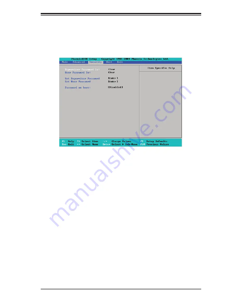
4-5 Security

Choose Security from the Phoenix BIOS Setup Utility main menu with the arrow 

keys.  You should see the following display.  Security setting options are displayed 

by highlighting the setting using the arrow keys and pressing <Enter>.  All Security 

BIOS settings are described in this section. 

Supervisor Password Is:

This feature indicates if a supervisor password has been entered to the system.  

Clear means such a password has not been used, and Set means a supervisor 

password has been entered.  

User Password Is:

This feature indicates if a user password has been entered to the system.  Clear 

means such a password has not been used, and Set means a user password has 

been entered.  

Set Supervisor Password

When the item Set "Supervisor Password" is highlighted, hit the <Enter> key.  When 

prompted,  type the Supervisor's password in the dialogue box to set or to change 

supervisor's password, which allows access to the BIOS.

Set User Password

When the item "Set User Password" is highlighted, hit the <Enter> key.  When 

prompted, type the user's password in the dialogue box to set or to change the 

user's password, which allows access to the system at boot-up.

Содержание X7DB8 Plus

Страница 1: ... X7DB8 X7DBE USER S MANUAL Revision 1 1a SUPER ...

Страница 2: ...tes Super Micro s total liability for all claims will not exceed the price paid for the hardware product FCC Statement This equipment has been tested and found to comply with the limits for a Class A digital device pursuant to Part 15 of the FCC Rules These limits are designed to provide reasonable protection against harmful interference when the equipment is operated in a commercial environment T...

Страница 3: ...DP enterprise server workstation environments This product is intended to be professionally installed Manual Organization Chapter 1 describes the features specifications and performance of the main board and provides detailed information about the chipset Chapter 2 provides hardware installation instructions Read this chapter when installing the processor memory modules and other hardware componen...

Страница 4: ...ss 1 10 1 4 PC Health Monitoring 1 10 1 5 ACPI Features 1 11 1 6 Power Supply 1 12 1 7 Super I O 1 13 Chapter 2 Installation 2 1 Static Sensitive Devices 2 1 Precautions 2 1 Unpacking 2 1 2 2 Installing the Processor and the Heatsink 2 2 2 3 Installing DIMMs 2 6 2 4 Control Panel Connectors and IO Ports 2 8 A Back Panel Connectors IO Ports 2 8 B Front Control Panel 2 9 C Front Control Panel Pin De...

Страница 5: ...B Power Connector 2 22 VGA Connector 2 22 Compact Flash Card PWR Connector 2 23 SGPIO Headers 2 23 2 6 Jumper Settings 2 24 Explanation of Jumpers 2 24 GLAN Enable Disable 2 24 Clear CMOS 2 25 Watch Dog 2 25 SCSI Controller Enabled Disabled 2 26 SCSI Termination Enabled Dsiabled 2 26 3rd PWR Supply PWR Fault 2 27 VGA Enable Disable 2 27 Compact Flash Master Slave Enable Disable 2 28 I2C Bus to PCI...

Страница 6: ... 2 3 3 Frequently Asked Questions 3 3 3 4 Returning Merchandise for Service 3 4 Chapter 4 BIOS 4 1 Introduction 4 1 4 2 Running Setup 4 2 4 3 Main BIOS Setup 4 2 4 4 Advanced Setup 4 7 4 5 Security Setup 4 25 4 6 Boot Setup 4 26 4 7 Exit 4 27 Appendices Appendix A BIOS POST Messages A 1 Appendix B BIOS POST Codes B 1 Appendix C Intel HostRAID Setup Guidelines C 1 Appendix D Adaptec HostRAID Setup ...

Страница 7: ...ave all been included with your motherboard If anything listed here is damaged or missing contact your retailer All the following items are included in the Retail Box One 1 Super Micro Mainboard One 1 ribbon cable for IDE devices One 1 Serial Port cable One 1 USB cable One 1 floppy ribbon cable One 1 Ultra 320 SCSI cable X7DB8 only Four 4 SATA cables X7DB8 only Six 6 SATA cables X7DBE only One 1 I...

Страница 8: ...per Micro Computer B V Het Sterrenbeeld 28 5215 ML s Hertogenbosch The Netherlands Tel 31 0 73 6400390 Fax 31 0 73 6416525 Email sales supermicro nl General Information support supermicro nl Technical Support rma supermicro nl Customer Support Asia Pacific Address Super Micro Computer Inc 4F No 232 1 Liancheng Road Chung Ho 235 Taipei Hsien Taiwan R O C Tel 886 2 8226 3990 Fax 886 2 8226 3991 Web ...

Страница 9: ... Note The drawings and pictures shown in this manual were based on the latest PCB Revision available at the time of publishing of the manual The motherboard you ve received may or may not look exactly the same as the graphics shown in the manual ...

Страница 10: ... VGA COM1 Fan5 ATX PWR 4 Pin PWR JP3 Parrallel Port 24 Pin JPG1 SCSI CTRL PXH CPU1 CPU2 South Bridge Fan7 JAR J17 JPW2 JPW1 JPW3 Fan2 JD1 JIDE1 JIDE2 Compact Flash LE1 Fan8 JCF1 JWF1 JPA2 JPA3 J22 JA1 JA2 JPA1 320 SCSI Channel B SATA2 SATA4 SATA1 SATA0 JL1 JK1 Slot1 J12 J13 J14 Slot2 Slot3 PCI X 133 MHz J9 Slot4 JPL1 JPL2 J6 Slot5 PCI Exp x4 Slot6 PCI Exp x8 J5 J11 SEPC SIMLPIPMI J16 Slot7 J9B1 J9...

Страница 11: ... 3 pin Fans1 4 4 pin Fans5 8 Fans7 8 CPU Fans FP CTRL JF1 Front Control Panel Connector Floppy J22 Floppy Disk Drive Connector GLAN 1 2 JLAN1 2 G bit Ethernet Ports IDE1 IDE2 Note IDE1 Hard Drive JIDE1 Compact Flash Card JIDE2 Keylock JK1 Keylock Header OH LED JOH1 Overheat LED Parallel Port J21 Parallel Printer Port PWR LED Speaker JD1 PWR LED pins1 3 Speaker Header pins 4 7 PWR LED LE1 PWR LED I...

Страница 12: ... slot BIOS 8 Mb Phoenix Flash ROM DMI 2 3 PCI 2 2 ACPI 1 0 Plug and Play PnP RTC Real Time Clock Wakeup PC Health Monitoring Onboard voltage monitors for CPU cores chipset voltage 3 3V 5V 5V Standby 12V and 12V Fan status monitor with firmware control CPU chassis temperature monitors Platform Environment Control Interface PECI ready CPU fan auto off in sleep mode CPU slow down on temperature overh...

Страница 13: ... floppy port interface Two COM ports 1 header 1 port One EPP ECP Parallel Port PS 2 mouse and PS 2 keyboard ports Up to five USB 2 0 Universal Serial Bus 2 ports 3 Headers ES1000 with 16 MB Graphic Controller Super I O Winbond W83627HF w Hardware Monitor support W83793 HECETA Other External modem ring on Wake on LAN WOL Wake on Ring WOR Console redirection Onboard Fan Speed Control by Thermal Mana...

Страница 14: ...X8 PCI EXP X8 PC I 33 S AT A 0 5 PCI E X8 PCI E X4 GILGAL GB LAN FWH RJ 45 RJ 45 LPC CO M SI O W83627 US B S EPC I DE CONN ATA 100 KB VGA CONN KUM ERAN US B 2 0 3 0Gb S VRM I SL6307 VRM I SL 6307 PROCESSOR 1 1067 1333 1067 1333 PARALLEL PORT 6 HF 4 PCI EXP X4 PCI EXPX8 5 PCI E XP X8 S L OT 3 PCI X SCSI 7902 2 PXH PCI X S l o t Z CR PCI X133A PC I X 133 PCI X133 B PCI X S l o t 4 0 S l o t MS 1 2 P...

Страница 15: ...subsys tem PXH The 5000P MCH chipset is designed for symmetric multiprocessing across two inde pendent front side bus interfaces Each front side bus uses a 64 bit wide 1333 MHz data bus that transfers data at 10 7 GB sec In addition the 5000P chipset offers a wide range of RAS features including memory interface ECC x4 x8 Single Device Data Correction CRC parity protection memory mirroring and mem...

Страница 16: ...ll scan these voltages continuously Once a voltage becomes unstable a warning is given or an error message is sent to the screen Users can adjust the voltage thresholds to define the sensitivity of the voltage monitor Fan Status Monitor with Firmware Control The PC health monitor can check the RPM status of the cooling fans The onboard CPU and chassis fans are controlled by Thermal Management via ...

Страница 17: ...nge 1 5 ACPI Features ACPI stands for Advanced Configuration and Power Interface The ACPI specifi cation defines a flexible and abstract hardware interface that provides a standard way to integrate power management features throughout a PC system including its hardware operating system and application software This enables the system to automatically turn on and off peripherals such as CD ROMs net...

Страница 18: ...gement application to remotely power up a computer that is powered off Remote PC setup up dates and asset tracking can occur after hours and on weekends so that daily LAN traffic is kept to a minimum and users are not interrupted The motherboard has a 3 pin header WOL to connect to the 3 pin header on a Network Interface Card NIC that has WOL capability In addition an onboard LAN controller can al...

Страница 19: ...rive interface control logic and interrupt and DMA logic The wide range of functions integrated onto the Super I O greatly reduces the number of components required for interfacing with floppy disk drives The Super I O supports 360 K 720 K 1 2 M 1 44 M or 2 88 M disk drives and data transfer rates of 250 Kb s 500 Kb s or 1 Mb s It also provides two high speed 16550 compatible serial communication ...

Страница 20: ...1 14 X7DB8 X7DBE User s Manual Notes ...

Страница 21: ... not touch its components peripheral chips memory modules or gold contacts When handling chips or modules avoid touching their pins Put the motherboard and peripherals back into their antistatic bags when not in use For grounding purposes make sure your computer chassis provides excellent conductivity between the power supply the case the mounting fasteners and the motherboard Use only the correct...

Страница 22: ...stall the CPU heatsink 2 Intel s boxed Xeon CPU package contains the CPU fan and heatsink assembly If you buy a CPU separately make sure that you use only Intel certified multi di rectional heatsink and fan 3 The Intel Xeon LGA 771 heatsink and fan comes with a push pin design and no tool is needed for installation 4 Make sure to install the motherboard into the chassis before you install the CPU ...

Страница 23: ... the socket Do not move the CPU horizontally or vertically Do not rub the CPU against the surface or against any pins of the socket to avoid damage to the CPU or the socket 7 With the CPU inside the socket inspect the four corners of the CPU to make sure that the CPU is properly installed 8 Use your thumb to gently push the socket clip down to the clip lock 9 If the CPU is properly installed into ...

Страница 24: ...on the retention mechanism 3 Screw in two diagonal screws ie the 1 and the 2 screws until just snug do not fully tighten the screws to avoid possible damage to the CPU 4 Finish the installation by fully tightening all four screws CEK Heatsink Installation Screw 2 Warning We do not recommend that the CPU or the heatsink be removed However if you do need to uninstall the heatsink please follow the i...

Страница 25: ...e precautionary measures to prevent damage done to these components when you install the motherboard to the chassis 1 Unscrew and remove the heatsink screws from the motherboard in the sequence as show in the picture on the right 2 Hold the heatsink as shown in the picture on the right and gently wriggle the heatsink to loosen it from the CPU Do not use excessive force when wriggling the heatsink ...

Страница 26: ...ly buffered FBD ECC DDR 2 533 667 in 16 DIMMs Populating DIMM modules with pairs of memory modules that are of the same size and same type in both Branch 0 and Branch 1 will result in interleaved memory See the table below Note 1 Due to OS limitations some operating systems may not show more than 4 GB of memory DIMM Module Population Configuration To optimize memory support follow the table below ...

Страница 27: ...ning available for operational use will be reduced when 4 GB of RAM is used The reduction in memory availability is disproportional See the Memory Availability Table below Possible System Memory Allocation Availability System Device Size Physical Memory Remaining Available 4 GB Total System Memory Firmware Hub flash memory System BIOS 1 MB 3 99GB Local APIC 4 KB 3 99GB Area Reserved for the chipse...

Страница 28: ...elow for the colors and locations of the various I O ports A Back Panel Connectors IO Ports Back Panel I O Port Locations and Definitions Back Panel Connectors 1 Keyboard Purple 2 PS 2 Mouse Green 3 Back Panel USB Port 0 4 Back Panel USB Port 1 5 COM Port 1 Turquoise 6 VGA Port Blue 7 Parallel Port Printer 8 Gigabit LAN 1 9 Gigabit LAN 2 See Section 2 5 for details 1 2 3 4 5 6 7 8 9 ...

Страница 29: ...nectors are designed specifically for use with Super Micro server chassis See the figure below for the descriptions of the various control panel buttons and LED indicators Refer to the following section for descriptions and pin definitions JF1 Header Pins Power Button OH Fan Fail LED 1 NIC1 LED Reset Button 2 HDD LED Power LED Reset PWR Vcc Vcc Vcc Vcc Ground Ground 19 20 Vcc X Ground NMI X Vcc PW...

Страница 30: ...Bank 3 DIMM 3D Bank 3 DIMM 2B Bank 2 DIMM 2C Bank 2 DIMM 2A Bank 2 DIMM 2D Bank 2 DIMM 1B Bank 1 DIMM 1C Bank 1 DIMM 1A Bank 1 DIMM 1D Bank 1 JUSB3 DA2 JWOL JP1 CTRL VGA SI O DA1 KB Mouse USB0 1 GLAN1 GLAN2 PWRSMB PWR Fault 3rdPWR Detect CTRL SGPIO1 SGPIO2 J28 J27 Power LED The Power LED connection is located on pins 15 and 16 of JF1 Refer to the table on the right for pin definitions NMI Button T...

Страница 31: ...Pin Definitions JF1 Pin Definition 9 11 Vcc 10 12 Ground A B C A HDD LED B NIC1 LED C NIC2 LED Introdu JLAN1 SUPER X7DB8 Fan1 8 pin PWR FP Ctrl SPK PW LED JOH1 Fan3 IDE1 Floppy BIOS 320 SCSI Channel A Fan4 SATA3 SATA5 USB2 3 SMB PCI X 100 MHz ZCR PCI X 133 MHz JWD Battery LAN PCI Exp x8 North Bridge VGA COM1 Fan5 ATX PWR 4 Pin PWR Parrallel Port 24 Pin JPG1 SCSI CTRL PXH CPU1 CPU2 South Bridge Fan...

Страница 32: ...und A B A OH Fan Fail LED B PWR Supply Fail Introdu JLAN1 SUPER X7DB8 Fan1 8 pin PWR FP Ctrl SPK PW LED JOH1 Fan3 IDE1 Floppy BIOS 320 SCSI Channel A Fan4 SATA3 SATA5 USB2 3 SMB PCI X 100 MHz ZCR PCI X 133 MHz JWD Battery LAN PCI Exp x8 North Bridge VGA COM1 Fan5 ATX PWR 4 Pin PWR Parrallel Port 24 Pin JPG1 SCSI CTRL PXH CPU1 CPU2 South Bridge Fan7 JAR Fan2 Compact Flash LE1 Fan8 JCF1 JWF1 JPA2 JP...

Страница 33: ...in definitions Reset Button Pin Definitions JF1 Pin Definition 3 Reset 4 Ground A Reset Button B PWR Button A B Introdu JLAN1 SUPER X7DB8 Fan1 8 pin PWR FP Ctrl SPK PW LED JOH1 Fan3 IDE1 Floppy BIOS 320 SCSI Channel A Fan4 SATA3 SATA5 USB2 3 SMB PCI X 100 MHz ZCR PCI X 133 MHz JWD Battery LAN PCI Exp x8 North Bridge VGA COM1 Fan5 ATX PWR 4 Pin PWR Parrallel Port 24 Pin JPG1 SCSI CTRL PXH CPU1 CPU2...

Страница 34: ...O2 J28 J27 2 5 Connecting Cables ATX Power Connector There are a 24 pin main power sup ply connector JPW1 and an 8 pin CPU PWR connector JPW3 on the motherboard These power connec tors meet the SSI EPS 12V specifica tion The 4 pin 12V PWR supply is required to provide adequate power to the system See the table on the right for pin definitions For the 8 pin PWR JPW3 please refer to the item listed ...

Страница 35: ...k 1 DIMM 1D Bank 1 JUSB3 DA2 JWOL JP1 CTRL VGA SI O DA1 KB Mouse USB0 1 GLAN1 GLAN2 PWRSMB PWR Fault 3rdPWR Detect CTRL SGPIO1 SGPIO2 J28 J27 Universal Serial Bus USB There are five USB 2 0 Universal Se rial Bus ports headers on the moth erboard Two of them are Back Panel USB ports USB 0 1 JUSB1 and the other three are Front Panel USB headers USB 2 3 JUSB2 USB 4 JUSB3 See the tables on the right f...

Страница 36: ... CTRL VGA SI O DA1 KB Mouse USB0 1 GLAN1 GLAN2 PWRSMB PWR Fault 3rdPWR Detect CTRL SGPIO1 SGPIO2 J28 J27 Fan Headers The X7DB8 X7DBE has six chassis system fan headers Fan1 to Fan6 and two CPU Fans Fans 7 8 Note Fans 5 6 7 8 are 4 pin fans However Pins 1 3 of these fan headers are backward compatible with the traditional 3 pin fans See the table on the right for pin defini tions The onboard fan sp...

Страница 37: ...C Bank 2 DIMM 2A Bank 2 DIMM 2D Bank 2 DIMM 1B Bank 1 DIMM 1C Bank 1 DIMM 1A Bank 1 DIMM 1D Bank 1 JUSB3 DA2 JWOL JP1 CTRL VGA SI O DA1 KB Mouse USB0 1 GLAN1 GLAN2 PWRSMB PWR Fault 3rdPWR Detect CTRL SGPIO1 SGPIO2 J28 J27 ATX PS 2 Keyboard and PS 2 Mouse Ports The ATX PS 2 keyboard and the PS 2 mouse are located at JKM1 See the table on the right for pin definitions The mouse port is above the key...

Страница 38: ...Introdu JLAN1 SUPER X7DB8 Fan1 8 pin PWR FP Ctrl SPK PW LED JOH1 Fan3 IDE1 Floppy BIOS 320 SCSI Channel A Fan4 SATA3 SATA5 USB2 3 SMB PCI X 100 MHz ZCR PCI X 133 MHz JWD Battery LAN PCI Exp x8 North Bridge VGA COM1 Fan5 ATX PWR 4 Pin PWR Parrallel Port 24 Pin JPG1 SCSI CTRL PXH CPU1 CPU2 South Bridge Fan7 JAR Fan2 Compact Flash LE1 Fan8 JCF1 JWF1 JPA2 JPA3 JPA1 320 SCSI Channel B SATA2 SATA4 SATA1...

Страница 39: ...ank 3 DIMM 3A Bank 3 DIMM 3D Bank 3 DIMM 2B Bank 2 DIMM 2C Bank 2 DIMM 2A Bank 2 DIMM 2D Bank 2 DIMM 1B Bank 1 DIMM 1C Bank 1 DIMM 1A Bank 1 DIMM 1D Bank 1 JUSB3 DA2 JWOL JP1 CTRL VGA SI O DA1 KB Mouse USB0 1 GLAN1 GLAN2 PWRSMB PWR Fault 3rdPWR Detect CTRL SGPIO1 SGPIO2 J28 J27 Power LED Speaker On the JD1 header pins 1 3 are for a power LED and pins 4 7 are for the speaker See the table on the ri...

Страница 40: ...1D Bank 1 JUSB3 DA2 JWOL JP1 CTRL VGA SI O DA1 KB Mouse USB0 1 GLAN1 GLAN2 PWRSMB PWR Fault 3rdPWR Detect CTRL SGPIO1 SGPIO2 J28 J27 Power Fault PWR Supply Failure Connect a cable from your power sup ply to the Power Fail header to provide warnings of power supply failure This warning signal is passed through the PWR_LED pin to indicate of a power failure on the chassis See the table on the right ...

Страница 41: ...3 DIMM 3C Bank 3 DIMM 3A Bank 3 DIMM 3D Bank 3 DIMM 2B Bank 2 DIMM 2C Bank 2 DIMM 2A Bank 2 DIMM 2D Bank 2 DIMM 1B Bank 1 DIMM 1C Bank 1 DIMM 1A Bank 1 DIMM 1D Bank 1 JUSB3 DA2 JWOL JP1 CTRL VGA SI O DA1 KB Mouse USB0 1 GLAN1 GLAN2 PWRSMB PWR Fault 3rdPWR Detect CTRL SGPIO1 SGPIO2 J28 J27 SMB A System Management Bus header is located at J18 Connect the appropri ate cable here to utilize SMB on you...

Страница 42: ...C Bank 4 J7 JBT1 USB4 JWOR JCOM2 Fan6 DIMM 4A Bank 4 DIMM 4D Bank 4 DIMM 3B Bank 3 DIMM 3C Bank 3 DIMM 3A Bank 3 DIMM 3D Bank 3 DIMM 2B Bank 2 DIMM 2C Bank 2 DIMM 2A Bank 2 DIMM 2D Bank 2 DIMM 1B Bank 1 DIMM 1C Bank 1 DIMM 1A Bank 1 DIMM 1D Bank 1 JUSB3 DA2 JWOL JP1 CTRL VGA SI O DA1 KB Mouse USB0 1 GLAN1 GLAN2 PWRSMB PWR Fault 3rdPWR Detect CTRL SGPIO1 SGPIO2 J28 J27 Power SMB I2 C Connector Powe...

Страница 43: ...A Bank 1 DIMM 1D Bank 1 JUSB3 DA2 JWOL JP1 CTRL VGA SI O DA1 KB Mouse USB0 1 GLAN1 GLAN2 PWRSMB PWR Fault 3rdPWR Detect CTRL SGPIO1 SGPIO2 J28 J27 A A Compact Flash PWR B SGPIO Headers Compact Flash Card PWR Connector A Compact Flash Card Power Connector is located at JWF1 For the Compact Flash Card or the Compact Flash Jumper JCF1 to work properly you will need to connect the Compact Flash Card p...

Страница 44: ...MM 1B Bank 1 DIMM 1C Bank 1 DIMM 1A Bank 1 DIMM 1D Bank 1 JUSB3 DA2 JWOL JP1 CTRL VGA SI O DA1 KB Mouse USB0 1 GLAN1 GLAN2 PWRSMB PWR Fault 3rdPWR Detect CTRL SGPIO1 SGPIO2 J28 J27 2 6 Jumper Settings Explanation of Jumpers To modify the operation of the motherboard jumpers can be used to choose between optional settings Jumpers create shorts between two pins to change the function of the connecto...

Страница 45: ...SI O DA1 KB Mouse USB0 1 GLAN1 GLAN2 PWRSMB PWR Fault 3rdPWR Detect CTRL SGPIO1 SGPIO2 J28 J27 CMOS Clear JBT1 is used to clear CMOS Instead of pins this jumper consists of contact pads to prevent the accidental clearing of CMOS To clear CMOS use a metal object such as a small screwdriver to touch both pads at the same time to short the connection Always remove the AC power cord from the system be...

Страница 46: ... 1 DIMM 1D Bank 1 JUSB3 DA2 JWOL JP1 CTRL VGA SI O DA1 KB Mouse USB0 1 GLAN1 GLAN2 PWRSMB PWR Fault 3rdPWR Detect CTRL SGPIO1 SGPIO2 J28 J27 A A SCSI Enable B SCSI Channel A Termi nation Enable C SCSI Channel B Termi nation Enable SCSI Controller Enable Disable Jumper JPA1 is used to enable or dis able the LSI SCSI controller The de fault setting is on pins 1 2 to enable SCSI See the table on the ...

Страница 47: ...2D Bank 2 DIMM 1B Bank 1 DIMM 1C Bank 1 DIMM 1A Bank 1 DIMM 1D Bank 1 JUSB3 DA2 JWOL JP1 CTRL VGA SI O DA1 KB Mouse USB0 1 GLAN1 GLAN2 PWRSMB PWR Fault 3rdPWR Detect CTRL SGPIO1 SGPIO2 J28 J27 3rd PWR Supply PWR Fault Detect J3P The system can notify you in the event of a power supply failure This feature avail able when three power supply units are installed in the chassis with one acting as a ba...

Страница 48: ...DIMM 1A Bank 1 DIMM 1D Bank 1 JUSB3 DA2 JWOL JP1 CTRL VGA SI O DA1 KB Mouse USB0 1 GLAN1 GLAN2 PWRSMB PWR Fault 3rdPWR Detect CTRL SGPIO1 SGPIO2 J28 J27 Compact Flash Master Slave Select ACompact Flash Master Primary Slave Secondary Select Jumper is located at JCF1 Close this jumper to enable Compact Flash Card For the Compact Flash Card or the Compact Flash Jumper JCF1 to work properly you will n...

Страница 49: ... Bank 3 DIMM 3D Bank 3 DIMM 2B Bank 2 DIMM 2C Bank 2 DIMM 2A Bank 2 DIMM 2D Bank 2 DIMM 1B Bank 1 DIMM 1C Bank 1 DIMM 1A Bank 1 DIMM 1D Bank 1 JUSB3 DA2 JWOL JP1 CTRL VGA SI O DA1 KB Mouse USB0 1 GLAN1 GLAN2 PWRSMB PWR Fault 3rdPWR Detect CTRL SGPIO1 SGPIO2 J28 J27 GLAN LEDs There are two GLAN ports on the moth erboard Each Gigabit Ethernet LAN port has two LEDs The yellow LED indicates activity w...

Страница 50: ...k 3 DIMM 3C Bank 3 DIMM 3A Bank 3 DIMM 3D Bank 3 DIMM 2B Bank 2 DIMM 2C Bank 2 DIMM 2A Bank 2 DIMM 2D Bank 2 DIMM 1B Bank 1 DIMM 1C Bank 1 DIMM 1A Bank 1 DIMM 1D Bank 1 JUSB3 DA2 JWOL JP1 CTRL VGA SI O DA1 KB Mouse USB0 1 GLAN1 GLAN2 PWRSMB PWR Fault 3rdPWR Detect CTRL SGPIO1 SGPIO2 J28 J27 Onboard SCSI Activity LED Indicators X7DB8 only There are two Onboard SCSI Activity LED indicators on the X7...

Страница 51: ...LAN1 GLAN2 PWRSMB PWR Fault 3rdPWR Detect CTRL SGPIO1 SGPIO2 J28 J27 Parallel Printer Port Connector The parallel printer port is located on the IO panel See the table on the right for pin definitions 2 8 Parallel Port Floppy Drive Hard Disk Drive SIMLP IPMI and SCSI Connections Note the following when connecting the floppy and hard disk drive cables The floppy disk drive cable has seven twisted w...

Страница 52: ...ion A B A Floppy B SIMLP IPMI 2 0 Introdu JLAN1 SUPER X7DB8 Fan1 8 pin PWR FP Ctrl SPK PW LED JOH1 Fan3 IDE1 Floppy BIOS 320 SCSI Channel A Fan4 SATA3 SATA5 USB2 3 SMB PCI X 100 MHz ZCR PCI X 133 MHz JWD Battery LAN PCI Exp x8 North Bridge VGA COM1 Fan5 ATX PWR 4 Pin PWR Parrallel Port 24 Pin JPG1 SCSI CTRL PXH CPU1 CPU2 South Bridge Fan7 JAR Fan2 Compact Flash LE1 Fan8 JCF1 JWF1 JPA2 JPA3 JPA1 32...

Страница 53: ...finition Pin Definition 1 Reset IDE 2 Ground 3 Host Data 7 4 Host Data 8 5 Host Data 6 6 Host Data 9 7 Host Data 5 8 Host Data 10 9 Host Data 4 10 Host Data 11 11 Host Data 3 12 Host Data 12 13 Host Data 2 14 Host Data 13 15 Host Data 1 16 Host Data 14 17 Host Data 0 18 Host Data 15 19 Ground 20 Key 21 DRQ3 22 Ground 23 I O Write 24 Ground 25 I O Read 26 Ground 27 IOCHRDY 28 BALE 29 DACK3 30 Groun...

Страница 54: ...Definition Pin Definition 1 DB 12 35 DB 12 2 DB 13 36 DB 13 3 DB 14 37 DB 14 4 DB 15 38 DB 15 5 DB P1 39 DB P1 6 DB 0 40 DB 0 7 DB 1 41 DB 1 8 DB 2 42 DB 2 9 DB 3 43 DB 3 10 DB 4 44 DB 4 11 DB 5 45 DB 5 12 DB 6 46 DB 6 13 DB 7 47 DB 7 14 DB P 48 DB P 15 Ground 49 Ground 16 DIFFSENS 50 Ground 17 TERMPWR 51 TERMPWR 18 TERMPWR 52 TERMPWR 19 Reserved 53 Reserved 20 Ground 54 Ground 21 ATN 55 ATN 22 Gr...

Страница 55: ... jumper settings as well 5 Use only the correct type of CMOS onboard battery as recommended by the Manufacturer Do not install the onboard battery upside down to avoid pos sible explosion No Power 1 Make sure that there are no short circuits between the motherboard and the chassis 2 Verify that all jumpers are set to their default positions 3 Check that the 115V 230V switch on the power supply is ...

Страница 56: ...module between four slots and noting the results 5 Make sure all memory modules are fully seated in their slots As an interleaved memory scheme is used you must install four modules at a time beginning with Branch 1 then Branch 2 and so on see Page 2 6 6 Check the position of the 115V 230V switch on the power supply 3 2 Technical Support Procedures Before contacting Technical Support please take t...

Страница 57: ...f you are not experiencing any problems with your system Updated BIOS files are located on our web site at http www supermicro com support bios Please check our BIOS warning message and the information on how to update your BIOS on our web site Select your moth erboard model and download the BIOS file to your computer Also check the current BIOS revision and make sure that it is newer than your BI...

Страница 58: ...fore any warranty service will be rendered You can obtain service by calling your vendor for a Returned Merchandise Authorization RMA number When returning to the manufacturer the RMA number should be prominently displayed on the outside of the shipping carton and mailed prepaid or hand carried Shipping and handling charges will be applied for all orders that must be mailed when service is complet...

Страница 59: ...ed off a backup battery pro vides power to the CMOS Logic enabling it to retain system parameters When the computer is powered on the computer is configured with the values stored in the CMOS Logic by the system BIOS which gains control at boot up How To Change the Configuration Data The CMOS information that determines the system parameters may be changed by entering the BIOS Setup utility This S...

Страница 60: ...BIOS is immediately acti vated While the BIOS is in control the Setup program can be activated in one of two ways 1 By pressing Delete immediately after turning the system on or 2 When the message shown below appears briefly at the bottom of the screen during the POST Power On Self Test press the Delete key to activate the main Setup menu Press the Delete key to enter Setup 4 3 Main BIOS Setup All...

Страница 61: ...te Using the arrow keys highlight the month day and year fields and enter the correct data Press the Enter key to save the data BIOS Date This field displays the date when this version of BIOS was built Legacy Diskette A This setting allows the user to set the type of floppy disk drive installed as diskette A The options are Disabled 360Kb 5 25 in 1 2MB 5 25 in 720Kb 3 5 in 1 44 1 25MB 3 5 in and ...

Страница 62: ...This option allows the user to selects the type of IDE hard drive The option Auto will allow the BIOS to automatically configure the parameters of the HDD installed at the connection Enter a number between 1 to 39 to select a predetermined HDD type Select User to allow the user to enter the parameters of the HDD installed Select CDROM if a CDROM drive is installed Select ATAPI if a removable disk ...

Страница 63: ...llows the user to enable or disable the function of 32 bit data transfer The options are Enabled and Disabled Transfer Mode This option allows the user to set the transfer mode The options are Standard Fast PIO1 Fast PIO2 Fast PIO3 Fast PIO4 FPIO3 DMA1 and FPIO4 DMA2 Ultra DMA Mode This option allows the user to select Ultra DMA Mode The options are Disabled Mode 0 Mode 1 Mode 2 Mode 3 Mode 4 and ...

Страница 64: ...d by the Windows 2000 OS or a later version When the SATA Controller Mode is set to Enhanced the following items will display Serial ATA SATA RAID Enable Select Enable to enable Serial ATA RAID Functions For the Windows OS environment use the RAID driver if this feature is set to Enabled When this item is set to Enabled the item ICH RAID Code Base will be available for you to select either Intel o...

Страница 65: ...ry This display informs you how much extended memory is recognized as being present in the system 4 4 Advanced Setup ChooseAdvancedfromthe PhoenixBIOSSetupUtilitymainmenuwiththearrowkeys You should see the following display The items with a triangle beside them have sub menus that can be accessed by highlighting the item and pressing Enter ...

Страница 66: ...nstant Off the system will power off immediately as soon as the user hits the power button If set to 4 sec the system will power off when the user presses the power button for 4 seconds or longer The options are instant off and 4 sec override Resume On Modem Ring Select On to wake your system up when an incoming call is received by your modem The options are On and Off Power Loss Control This sett...

Страница 67: ...ffer and written into the system memory at the same time Select Write Protect to prevent data from being written into the base memory area of Block 0 512K Select Write Back to allow the CPU to write data back directly from the buffer without writing data to the System Memory for fast CPU data processing and operation The options are Uncached Write Through Write Protect and Write Back Cache Base 51...

Страница 68: ...ard GLAN1 Onboard GLAN2 Gigabit LAN OPROM Configure Enabling this option provides the capability to boot from GLAN The options are Disabled and Enabled Onboard SCSI OPROM Configure Enabling this option provides the capitally to boot from SCSI HDD The options are Disabled and Enabled PCI Parity Error Forwarding The feature allows SERR and PERR errors detected in PCI slots to be sent forwarded to th...

Страница 69: ...lation of a new software you might want to change this setting and try again A different OS requires a different Bus Master clock rate Large Disk Access Mode This setting determines how large hard drives are to be accessed The options are DOS or Other for Unix Novelle NetWare and other operating systems XAdvanced Chipset Control Access the submenu to make changes to the following settings Warning ...

Страница 70: ...Technology to accelerate the performance of TOE devices Note A TOE device is a specialized dedicated processor that is installed on an add on card or a network card to handle some or all packet processing of this add on card For the X7DB8 E the TOE device is built inside the ESB 2 South Bridge chip The options are Enabled and Disabled Route Port 80h Cycles to This feature allows the user to decide...

Страница 71: ...able when supported by the CPU Set to Enabled to use Thermal Management 2 TM2 which will lower CPU voltage and frequency when the CPU temperature reaches a predefined overheat threshold Set to Disabled to use Thermal Manager 1 TM1 allowing CPU clocking to be regulated via CPU Internal Clock modulation when the CPU temperature reaches the overheat threshold C1 Enhanced Mode Available when supported...

Страница 72: ... one platform to run multiple operating systems and applications in independent partitions creating multiple virtual systems in one physical computer The options are Enabled and Disabled Note If there is any change to this setting you will need to power off and restart the system for the change to take effect Please refer to Intel s web site for detailed information Intel EIST Support Available wh...

Страница 73: ...Port This setting allows you to assign control of the parallel port The options are Enabled user defined Disabled and Auto BIOS or OS controlled Base I O Address Select the base I O address for the parallel port The options are 378 278 and 3BC Interrupt This setting allows you to select the IRQ interrupt request for the parallel port The options are IRQ5 and IRQ7 Mode This feature allows you to sp...

Страница 74: ...g capacity It is not a setting View DMI Event Log Highlight this item and press Enter to view the contents of the event log Event Logging This setting allows you to Enable or Disable event logging ECC Event Logging This setting allows you to Enable or Disable ECC event logging Mark DMI Events as Read Highlight this item and press Enter to mark the DMI events as read Clear All DMI Event Logs Select...

Страница 75: ...0 2400 9600 19 2K 38 4K 57 6K and 115 2K Console Type This item allows you to set console redirection type The options are VT100 VT100 8bit PC ANSI 7bit PC ANSI VT100 VT UTF8 and ASCII Flow Control This item allows you to select the flow control option for console redirection The options are None XON XOFF and CTS RTS Console Connection This item allows you to decide how console redirection is to b...

Страница 76: ...oard fans The CPU temperature and the fan speed are correlative When the CPU on die temperature increases the fan speed will also increase and vice versa Select Workstation if your system is used as a Workstation Select Server if your system is used as a Server Select 3 pin if your chassis uses 3 pin fans Select 4 pin if your chassis uses 4 pin fans Select Disable to disable the fan speed control ...

Страница 77: ...ect Workstation if your system is used as a Workstation Select Server if your system is used as a Server Select 3 pin if your chassis uses 3 pin fans Select 4 pin if your chassis uses 4 pin fans Select Disable to disable the fan speed control function and allow the onboard fans to constantly run at the full speed 12V The Options are 1 Disable 2 Optimized Server w 3 pin 3 Optimized Workstation w 3 ...

Страница 78: ... increase and vice versa Select Workstation if your system is used as a Workstation Select Server if your system is used as a Server Select 3 pin if your chassis uses 3 pin fans Select 4 pin if your chassis uses 4 pin fans Select Disable to disable the fan speed control function and allow the onboard fans to constantly run at the full speed 12V The Options are 1 Disable 2 Optimized Server w 3 pin ...

Страница 79: ...rface The options are Enabled and Disabled Clear System Event Logging Enabling this function to force the BIOS to clear the system event logs during the next cold boot The options are Enabled and Disabled Existing Event Log Number This item displays the number of the existing event log Event Log Control System Firmware Progress Enabling this function to log POST progress The options are Enabled an...

Страница 80: ...s option when OS Boot Watch Dog is set to Disabled Time Out Option This feature allows the user to determine what action to take in an event of a system boot failure The options are No Action Reset Power Off and Power Cycles XSystem Event Log System Event Log List Mode These options display the System Event SEL Log and System Event SEL Log in List Mode Items include SEL System Event Log Entry Numb...

Страница 81: ...r Data This feature display information from motherboard sensors such as temperatures fan speeds and voltages of various components XIPMI LAN Configuration The following features allow the user to configure and monitor IPMI LAN settings ...

Страница 82: ...tem allows the user to change the VLAN ID If VLAN Tagging is disabled this item will be ignored by the firmware IP Address This item displays the IP address for the IPMI connection detected IP Subnet Mask This item displays the IP Subnet Mask for the IPMI connection detected Default Gateway This item displays the Default Gateway for the IPMI connection detected MAC Address This item displays the M...

Страница 83: ... supervisor password has been entered User Password Is This feature indicates if a user password has been entered to the system Clear means such a password has not been used and Set means a user password has been entered Set Supervisor Password When the item Set Supervisor Password is highlighted hit the Enter key When prompted type the Supervisor s password in the dialogue box to set or to change...

Страница 84: ...ection above are bootable devices listed in the sequence of boot order as specified The boot functions for the devices included in the candidate list above are currently disabled Use a key or a key to move the device up or down Use the f key or the r key to specify the type of an USB device either fixed or removable You can select one item from the boot list and hit the x key to remove it from the...

Страница 85: ... Discarding Changes Highlight this item and hit Enter to exit the BIOS Setup utility without saving any changes you may have made Load Setup Defaults Highlight this item and hit Enter to load the default settings for all items in the BIOS Setup These are the safest settings to use Discard Changes Highlight this item and hit Enter to discard cancel any changes you made You will remain in the Setup ...

Страница 86: ...4 28 X7DB8 X7DBE User s Manual Notes ...

Страница 87: ...led Keyboard controller failed test May require replacing keyboard controller Keyboard locked Unlock key switch Unlock the system to proceed Monitor type does not match CMOS Run SETUP Monitor type not correctly identified in Setup Shadow Ram Failed at offset nnnn Shadow RAM failed at offset nnnn of the 64k block at which the error was de tected System RAM Failed at offset nnnn System RAM failed at...

Страница 88: ... POST did not complete successfully POST loads default values and offers to run Setup If the failure was caused by incorrect values and they are not corrected the next boot will likely fail On systems with control of wait states improper Setup settings can also terminate POST and cause this error on the next boot Run Setup and verify that the waitstate configuration is correct This error is cleare...

Страница 89: ...verBIOS2 test error Cannot generate software NMI Non Maskable Interrupt Fail Safe Timer NMI Failed ServerBIOS2 test error Fail Safe Timer takes too long device Address Conflict Address conflict for specified device Allocation Error for device Run ISA or EISA Configuration Utility to resolve resource conflict for the specified device CD ROM Drive CD ROM Drive identified Entering SETUP Starting Setu...

Страница 90: ...tested One or more I2O Block Storage Devices were excluded from the Setup Boot Menu There was not enough room in the IPL table to display all installed I2O block storage devices Operating system not found Operating system cannot be located on either drive A or drive C Enter Setup and see if fixed disk and drive A are properly identified Parity Check 1 nnnn Parity error found in the system bus BIOS...

Страница 91: ... Optional message displayed during POST Can be turned off in Setup PS 2 Mouse PS 2 mouse identified Run the I2O Configuration Utility One or more unclaimed block storage devices have the Configuration Request bit set in the LCT Run an I2O Configuration Utility e g the SAC utility System BIOS shadowed System BIOS copied to shadow RAM UMB upper limit segment address nnnn Displays the address nnnn of...

Страница 92: ...A 6 X7DB8 X7DBE User s Manual Notes ...

Страница 93: ... to initialize video and write the error in the top left corner of the screen The following is a list of codes that may be written to port 80h Appendix B BIOS POST Codes POST Code Description 01h IPMI Initialization 02h Verify Real Mode 03h Disable Non Maskable Interrupt NMI 04h Get CPU type 06h Initialize system hardware 07h Disable shadow and execute code from the ROM 08h Initialize chipset with...

Страница 94: ...h Shadow system BIOS ROM 3Ah Auto size cache 3Ch Advanced configuration of chipset registers 3Dh Load alternate registers with CMOS values 41h Initialize extended memory for RomPilot optional 42h Initialize interrupt vectors 45h POST device initialization 46h 2 1 2 3 Check ROM copyright notice 48h Check video configuration against CMOS 49h Initialize PCI bus and devices 4Ah Initialize all video ad...

Страница 95: ...and IRQs optional 81h Late POST device initialization 82h Detect and install external RS232 ports 83h Configure non MCD IDE controllers 84h Detect and install external parallel ports 85h Initialize PC compatible PnP ISA devices 86h Re initialize onboard I O ports 87h Configure Motherboard Configurable Devices optional 88h Initialize BIOS Data Area 89h Enable Non Maskable Interrupts NMIs 8Ah Initia...

Страница 96: ... prepare to boot operating system B4h 1 One short beep before boot B5h Terminate QuietBoot optional B6h Check password optional B7h Initialize ACPI BIOS and PPM Structures B9h Prepare Boot BAh Initialize SMBIOS BCh Clear parity checkers BDh Display MultiBoot menu BEh Clear screen optional BFh Check virus and backup reminders C0h Try to boot with INT 19 C1h Initialize POST Error Manager PEM C2h Ini...

Страница 97: ...type EDh Initialize Memory size EEh Shadow Boot Block EFh System memory test F0h Initialize interrupt vectors F1h Initialize Run Time Clock F2h Initialize video F3h Initialize System Management Manager F4h Output one beep F5h Clear Huge Segment F6h Boot to Mini DOS F7h Boot to Full DOS If the BIOS detects errors on 2C 2E or 30 base 512K RAM error it displays an additional word bitmap xxxx indicati...

Страница 98: ...B 6 X7DB8 X7DBE User s Manual Notes ...

Страница 99: ...ckaged with your motherboard Note that the current version of the ESB2 SATA RAID Utility can only support Windows XP 2000 2003 Operating Systems Serial ATA SATA Serial ATA SATA is a physical storage interface that uses a single cable with a minimum of four wires to create a point to point connection between devices It is a serial link which supports transfer rates up to 3 0 Gbps Because the serial...

Страница 100: ... RAID Functions Native Mode 1 Press the Del key during system bootup to enter the BIOS Setup Utility Note If it is the first time powering on the system we recommend you load the Optimized Default Settings If you have already done so please skip to Step 3 2 Use the arrow keys to select the Exit Settings Once in the Exit settings Scroll down to select Load Optimized Default Settings and press the E...

Страница 101: ... appears after Power On Self Test b When you see the above screen press the Ctrl and the I keys simultane ously to have the main menu of the SATA RAID Utility appear Note All graphics and screen shots shown in the manual are for reference only The screen shots shown in the manual do not imply Supernicro s endorsement or non en dorsement on any 3rd party s product Your screens may or many not look ...

Страница 102: ...and press Space to select it A triangle appears to confirm the selection of the drive f Use the Up Arrow Down Arrow keys to select the stripe size ranging from 4 KB to 128 KB for the RAID 0 array and hit Enter Note For a server please use a lower stripe size and for a multimedia system use a higher stripe size The default stripe size is 128 KB g Press Enter when the Create Volume item is highlight...

Страница 103: ...o select the previous menu c When RAID Level item is highlighted press the Up Arrow Down Arrow keys to select RAID 1 Mirror and hit Enter d When the Capacity item is highlighted enter your RAID volume capacity and hit Enter The default setting is the maximum capacity allowed e Press Enter when the Create Volume item is highlighted A warning message displays f When asked Are you sure you want to cr...

Страница 104: ... Arrow keys to select the stripe size from 4 KB to 128 KB for your RAID 10 and hit Enter The default setting is 64 KB Note For a server please use a lower stripe size and for a multimedia system use a higher stripe size e When the RAID Volume Capacity item is highlighted enter your RAID volume capacity and hit Enter The default setting is the maximum capacity allowed f Press Enter when the Create ...

Страница 105: ...light a drive and press Space to select it A triangle appears to confirm the selection of the drive f Use the Up Arrow Down Arrow keys to select the stripe size ranging from 4 KB to 128 KB for the RAID 5 array and hit Enter Note For a server please use a lower stripe size and for a multimedia system use a higher stripe size The default stripe size is 128 KB g Enter your desired RAID volume capacit...

Страница 106: ...es when deleting a RAID set a From the main menu select item2 Delete RAID Volume and press Enter b Use the Up Arrow Down Arrow keys to select the RAID set you want to delete and press Del A Warning message displays c When asked Are you sure you want to delete this volume Y N press Y to delete the RAID volume or type N to go back to the Delete Volume menu ...

Страница 107: ...the RAID set drive A Warning message displays d Press Y to reset the drive or type N to go back to the main menu Exiting the Intel Matrix Storage Manager Utility a From the main menu select item4 Exit and press Enter A warning message will appear b Press Y to reset the drive or type N to go back to the main menu Warning Be cautious when you reset a RAID volume HDD to non RAID or Resetting a RAID H...

Страница 108: ...nd press the Enter key e Choose the Intel R ESB2 SATA RAID Controller from the list indicated in the XP 2000 2003 Setup Screen and press the Enter key f Press the Enter key to continue the installation process If you need to specify any additional devices to be installed do it at this time Once all devices are speci fied press the Enter key to continue with the installation g From the Windows XP 2...

Страница 109: ...ed in smaller chassis than Parallel ATA In addition the cables used in PATA can only extend to 40cm long while Serial ATA cables can extend up to one meter Overall Serial ATA provides better functionality than Parallel ATA Introduction to the Intel ESB2 I O Controller Hub Located in the South Bridge of the Intel 5000P Chipset the ESB2 I O Controller Hub provides the I O subsystem with access to th...

Страница 110: ...nter key to load the default settings for the BIOS 3 Use the arrow keys to select the Main section in BIOS 4 Scroll down to SATA Control Mode and press the Enter key to select En hanced 5 Scroll down to SATA RAID Enabled and press Enter Then select En abled 6 Scroll down to ICH RAID Codebase and select Adaptec Then press Enter For ICH RAID Codebase Change the setting from Intel to Adaptec 7 Go to ...

Страница 111: ...cations Using the Adaptec RAID Configuration Utility ARC The Adaptec RAID Configuration Utility an embedded BIOS Utility includes the following Array Configuration Utility Use this utility to create configure and manage ar rays Disk Utilities Use this option to format or verify disks To run the Adaptec RAID Configuration Utility you will need to do the following 1 Enable RAID functions in the syst...

Страница 112: ...ser s Manual Managing Arrays Select this option to view array properties and configure array settings To select this option using the arrow keys and the enter key select Managing Arrays from the main menu as shown above ...

Страница 113: ...disk and may make any data on the disk inaccessible If the drive is used in an array you may not be able to use the array again Do not configure a disk that is part of a boot array To determine which disks are associated with a particular array please refer to Viewing Array Properties To configure a disk drive 1 From the main menu shown on Page D 4 select Configure Drives and hit Enter as shown be...

Страница 114: ... you want to configure and press Insert 3 The drive you ve selected will appear in the Selected Drives Dialog Box on the right as shown below Repeat the same steps until all drives that you want to configure appear in the selected drives box 4 Once both drives display in the selected drive box press Enter ...

Страница 115: ...endix D Adaptec HostRAID Setup Guidelines D 7 5 Read the warning message as shown in the screen below 6 Make sure that you have selected the correct disk drives to configure If cor rect type Y to continue ...

Страница 116: ...s recommended that you configure devices before you create arrays To create an array 1 From the main menu shown on page D 4 select Create Array 2 Select the disks for the new array and press Insert as the screen shown below Note To de select any disk highlight the disk and press Delete 3 The arrays you have selected will appear on the Selected Drives dialog box on the right as shown below 4 Press ...

Страница 117: ...e the default setting 4 The item Create RAID via allows you to select between the different ways of creating methods for RAID 0 and RAID 1 The following table gives examples of when each is appropriate Note If you select Migrate for RAID 0 or Build for RAID 1 you will be asked to select the source drive The contents of the source drive will be preserved However the data on the new drive will be lo...

Страница 118: ...zes in a RAID However you can only select a smaller drive as the source or first drive during a build operation 5 When migrating from single volume to RAID 0 migrating from a larger drive to a smaller drive is allowed However the destination drive must be at least half the capacity of the source drive 6 It is not recommended that you migrate or build an array on Windows dynamic disks volumes becau...

Страница 119: ...ed An asterisk will appear next to the bootable array as shown in the picture below Deleting a Bootable Array To delete a bootable array 1 From the Main menu select Manage Arrays 2 From the List of Arrays select the bootable array you want to delete and press Ctrl and B Note a bootable array is the array marked with an asterisk as shown in the picture above 3 When the following message is displaye...

Страница 120: ...nd press Insert and then press Enter 3 Press Yes when the following prompt is displayed Do you want to create spare Yes No The spare you have selected will appear in the Selected drives Menu To delete a Hotspare 1 From the main menu shown on Page D 4 select Add Delete Hotspares 2 Use the up and down arrow keys to highlight and select the Hotspare you want to delete and press delete and then press ...

Страница 121: ... Arrays and hit Enter as shown on the previous page 2 From the List of Arrays dialog box shown below select the array you want to view and press Enter The Array Properties dialog box appears as shown below showing detailed in formation on the array The physical disks associated with the array are displayed here 3 Press Esc to return to the previous menu ...

Страница 122: ...ebuild to restore its functionality For a critical array rebuild operation the optimal drive is the source drive Note 2 If no spare array exists and a hard disk drive fails you need to create a spare before you can rebuild an array To Rebuild an array 1 From the Main Menu select Manage Arrays as shown in the screen below From the List of Arrays select the array you want to Rebuild 2 Press Ctrl and...

Страница 123: ... to delete and press delete 3 In the Array Properties dialog box select Delete and press Enter The follow ing prompt is displayed Warning Deleting the array will render array unusable Do you want to delete the array Yes No RAID 1 only the following prompt is also displayed Deleting the partition will result in data loss Do you also want to delete the parti tion Yes No 4 Press Yes to delete the arr...

Страница 124: ... format or verify the media of your Serial ATA hard disks To access the disk utilities 1 From the Adaptec RAID Configuration Utility Menu select Disk Utilities as shown above and press Enter The following screen appears 2 Select the desired disk and press Enter The following screen appears ...

Страница 125: ...d at the factory and do not need to be low level formatted again 3 When the screen shown below displays select Format Disk and press Enter The following screen appears 4 Read the warning message when it appears in the screen as shown below To continue with disk formatting select Yes and hit Enter Otherwise select No and press Enter Caution Formatting a disk destroys all data on the drive Be sure t...

Страница 126: ...n the screen shown above displays select Verify Disk Media and press Enter 4 A message will display indicating that the selected drive will be scanned for me dia defects Select Yes and hit Enter to proceed with disk verifying otherwise select No and hit Enter ...

Страница 127: ...aptec HostRAID Setup Guidelines D 19 To Exit Adaptec RAID Configuration Utility 1 Once you have completed RAID array configurations press ESC to exit The following screen will appear 2 Press Yes to exit the Utility ...

Страница 128: ...the F6 key when the message Press F6 if you need to install a third party SCSI or RAID driver displays h When the Windows OS Setup screen appears press S to specify additional device s i Insert the driver diskette Adaptec Embedded Serial ATA Raid Controller Driver into Drive A and press the Enter key j Choose Adaptec Embedded Host Serial ATA Raid Controller from the list indicated in the Windows O...

Страница 129: ... system before proceeding with the next item on the list The bottom icon with a CD on it allows you to view the entire contents of the CD Appendix E Installing Other Software Programs and Drivers A Installing Drivers other than the Adaptec Embedded Serial ATA RAID Controller Driver After you ve installed the Windows Operating System a screen as shown below will appear You are ready to install soft...

Страница 130: ...splays crucial system information such as CPU temperature system voltages and fan status See the Figure below for a display of the Supero Doctor III interface Note 1 The default user name and password are ADMIN Note 2 In the Windows OS environment the Supero Doctor III settings take pre cedence over the BIOS settings When first installed Supero Doctor III adopts the temperature threshold settings ...

Страница 131: ...II Remote Control Note SD III Software Revision 1 0 can be downloaded from our Web site at ftp ftp supermicro com utility Supero_Doctor_III You can also download SDIII User s Guide at http www supermicro com PRODUCT Manuals SDIII UserGuide pdf For Linux we will still recommend that you use Supero Doctor II ...

Страница 132: ...E 4 X7DB8 X7DBE User s Manual Notes ...

Отзывы: