


34
Super X12STL-F User's Manual
BMC
JPG1
JWD1
I-SGPIO1
I-SGPIO2
M.2-P
M.2 NVME
I-SA
TA4
I-SA
TA3
I-SA
TA2
MEGERAC
LICENCE
BT1
CPU SLOT6 PCIe 4.0 x8 (IN x16)
PCH SLOT4 PCIe 3.0 x2 (IN x4)
CPU SLOT5 PCIe 4.0 x8
JBT1
REV:1.01
X12STL-F
JUIDB1
LED1
LEDM1
JPCIE7
FAN4
COM2
USB2/3
JIPMB1
JPME2
JPWR2
JPWR1
JPI2C1
JF1
USB6/7 (3.0)
JL1
JSD2
JSD1
USB8(3.0)
LED4
LED3
JSTBY1
FAN1
FAN2
FAN3
FANA
FANB
I-SATA1 I-SATA0
JPCIE6
JPCIE5
JPCIE4
JPCIE5
MH10
MH11
JTPM1
CPU SLOT7 PCIe 4.0 x4 (IN x8)
DIMMB1
DIMMA2
DIMMB2
DIMMA1
USB0/1
BMC_LAN
COM1
VGA
LAN2
LAN1
USB4/5
I-SA
TA5
CHASSIS INTRUSION
PWRI2C
DESIGNED IN USA
M.2
CPU
1
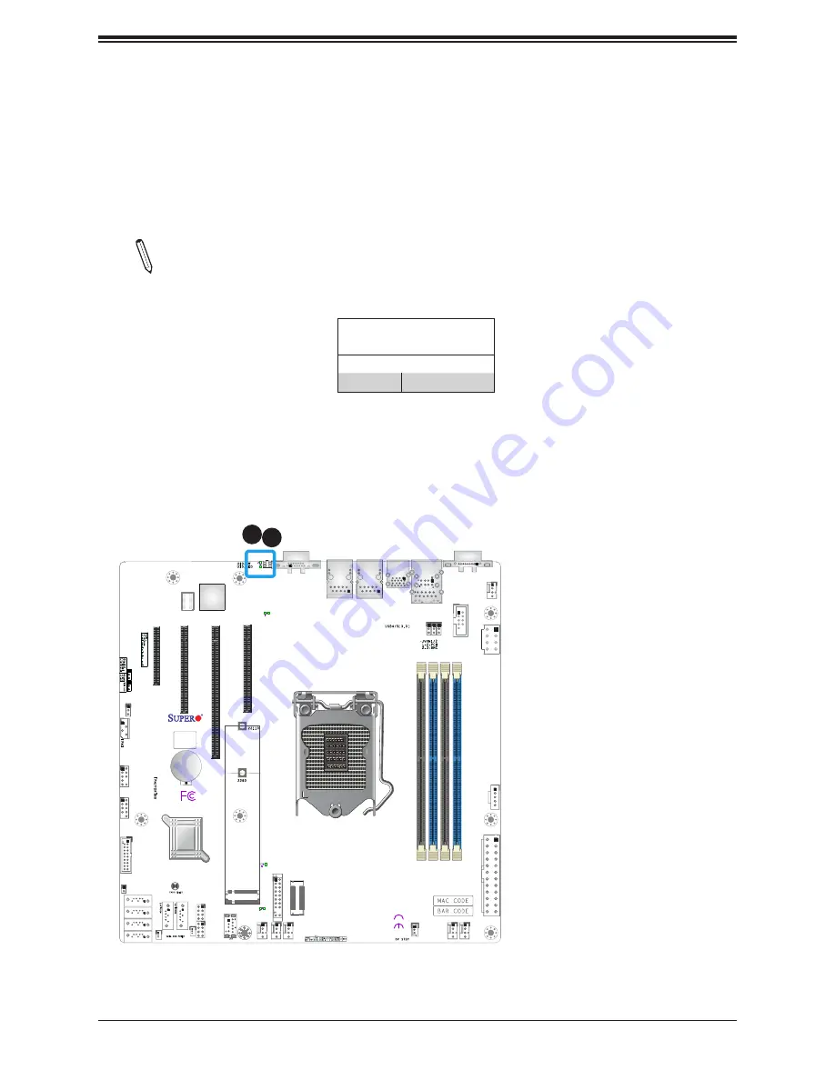
1. UID Switch
2. UID LED
2
Unit Identifier Switch/UID LED Indicator
A Unit Identifier (UID) switch and an LED indicator are located on the motherboard. The UID
switch is located at UID SW. The UID switch is located at JUIDB1, which is next to the VGA
port on the back panel. The UID LED (LED1) is located next to the UID switch. When you
press the switch, the LED will be turned on, which provides easy identification of a system
unit that may be in need of service. Press the switch again to turn off the LED indicator.
Note:
UID can also be triggered via BMC on the motherboard. For more information
on BMC, please refer to the BMC User's Guide posted on our website at
http://www.
supermicro.com/support/manuals/
.
UID LED
Pin Definitions
Color
Status
Blue: On
Unit Identified
Содержание X12STL-F
Страница 1: ...USER S MANUAL Revision 1 0 X12STL F ...


