background image

Chapter 4: BIOS

97

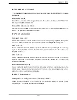
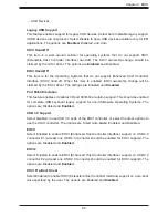
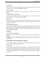
Recorder Mode

Select Enabled to capture the data displayed on a terminal and send it as text messages to 
a remote server. The options are 

Disabled

 and Enabled.

Resolution 100x31

Select Enabled for extended-terminal resolution support. The options are Disabled and 

Enabled

Legacy OS Redirection Resolution

Use this feature to select the number of rows and columns used in Console Redirection for 
legacy OS support. The options are


80x24 and 

80x25

.

Putty KeyPad

This feature selects the settings for Function Keys and KeyPad used for Putty, which is a 
terminal emulator designed for the Windows OS. The options are 

VT100

, LINUX, XTERMR6, 

SC0, ESCN, and VT400.

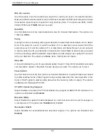
Redirection After BIOS POST

Use this feature to enable or disable legacy console redirection after BIOS POST. When set to 
Bootloader, legacy console redirection is disabled before booting the OS. When set to Always 
Enable, legacy console redirection remains enabled when booting the OS. The options are 

Always Enable

 and Bootloader.

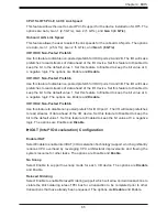
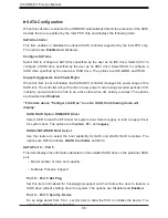
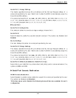
SOL/COM2

SOL/COM2 Console Redirection

Select Enabled to use the SOL port for Console Redirection. The options are


Disabled and


Enabled.

*If the item above set to Enabled, the following items will become available for user's 

configuration:

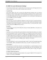
SOL/COM2 Console Redirection Settings

Use this feature to specify how the host computer will exchange data with the client computer, 
which is the remote computer used by the user.

Terminal Type

Use this feature to select the target terminal emulation type for Console Redirection. Select 
VT100 to use the ASCII Character set. Select VT100+ to add color and function key support. 
Select ANSI to use the Extended ASCII Character Set. Select VT-UTF8 to use UTF8 encoding 
to map Unicode characters into one or more bytes. The options are


ANSI, VT100, 

VT100+

and VT-UTF8.

Содержание X10SRM-F

Страница 1: ...USER MANUAL Revision 1 0a X10SRM F TF...

Страница 2: ...operated in a commercial environment This equipment generates uses and can radiate radio frequency energy and if not installed and used in accordance with the manufacturer s instruction manual may ca...

Страница 3: ...this motherboard is intended to be installed and serviced by professional technicians only For processor memory updates please refer to our website at http www supermicro com products Conventions Used...

Страница 4: ...uter B V Het Sterrenbeeld 28 5215 ML s Hertogenbosch The Netherlands Tel 31 0 73 6400390 Fax 31 0 73 6416525 Email sales supermicro nl General Information support supermicro nl Technical Support rma s...

Страница 5: ...Temperature Control 21 System Resource Alert 21 1 5 ACPI Features 21 1 6 Power Supply 22 1 7 Serial Port 22 Chapter 2 Installation 2 1 Static Sensitive Devices 23 Precautions 23 Unpacking 23 2 2 Moth...

Страница 6: ...No Video 68 System Boot Failure 68 Memory Errors 68 Losing the System s Setup Configuration 69 When the System Becomes Unstable 69 3 2 Technical Support Procedures 71 3 3 Frequently Asked Questions 7...

Страница 7: ...Software Installation B 1 Installing Software Programs 117 B 2 SuperDoctor 5 118 Appendix C Standardized Warning Statements Battery Handling 119 Product Disposal 121 Appendix D UEFI BIOS Recovery D 1...

Страница 8: ...8 X10SRM F TF User Manual Notes...

Страница 9: ...m are listed below If anything listed is damaged or missing please contact your retailer 1 1 Checklist Important Links For your system to work properly please follow the links below to download all ne...

Страница 10: ...therboard Image Note All graphics shown in this manual were based upon the latest PCB revision available at the time of publication of the manual The motherboard you received may or may not look exact...

Страница 11: ...11 Chapter 1 Introduction Figure 1 2 X10SRM TF Motherboard Image...

Страница 12: ...W1 FAN1 JPI2C1 FAN2 FAN3 FANA JPUSB1 USB10 3 0 USB8 9 3 0 USB4 5 I SGPIO2 I SGPIO1 JS1 JL1 USB2 3 JP3 JWD1 JPME2 JI2C2 JI2C1 JPB1 JBT1 BT1 JMD1 JNVI2C1 JIPMB1 LEDBMC LEDPWR LE8 LE1 JUIDB1 VGA JPCIE4 J...

Страница 13: ...D1 IPMI_LAN USB0 1 USB10 3 0 LAN1 USB6 7 3 0 LAN2 JCOM1 JVGA JUIDB1 LE1 JIPMB1 JPL1 JTPM1 FAN4 COM2 JSTBY1 JPV1 JPW1 JPI2C1 FAN2 FAN1 JVRM2 JPH2 FAN3 I SATA5 USB8 9 3 0 SP1 DIMMC1 DIMMA1 DIMMD1 DIMMB1...

Страница 14: ...LE8 HDD Access LED Green On HDD detected LEDBMC BMC Heartbeat LED Green Blinking BMC normal LEDPWR Onboard Power LED Green Solid on Power on Connector Description BT1 Onboard Battery COM1 COM2 COM Por...

Страница 15: ...ed Platform Module Port 80 Connector JUIDB1 UID Switch LAN1 LAN2 LAN RJ45 Ports SP1 Internal Speaker Buzzer SRW3 M 2 42mm card holding screw SRW4 M 2 80mm card holding screw SRW5 M 2 110mm card holdin...

Страница 16: ...e latest CPU memory updates please refer to our website at http www supermicro com products motherboard Chipset Intel PCH C612 Expansion Slots Two 2 PCI Express 3 0 x8 slots CPU1 Slot4 CPU1 Slot5 Note...

Страница 17: ...USB 3 0 header with two 2 USB connections USB8 9 One 1 Type A USB 3 0 header USB10 BIOS 128Mb AMI BIOS SPI Flash BIOS ACPI 3 0 or later Plug and Play PnP BIOS rescue hot key Riser Card auto detection...

Страница 18: ...ermal management please check the chas sis and heatsink specifications for proper CPU TDP sizing Note 2 For IPMI configuration instructions please refer to the Embedded IPMI Con figuration User s Guid...

Страница 19: ...average 2 3W Peak TDP 5W SERVER Idle 0 45W 5V 1 2A 3 3V 0 1A 3 3 STBY 0 2A 1 05 PCH 1 05 ASW 1 5 PCH PVCCIO 1 0 0 95 3 3STBY 0 5A PCI E X8 G3 i350 JLAN1 3 CPU0 S SATA 0 3 I SATA 6 0 Gb S SPI Switch SP...

Страница 20: ...port for Management Engine ME Support of SMBus speeds of up to 400KHz for BMC connectivity Improved I O capabilities to high storage capacity configurations SPI Enhancements Intel Node Manager 3 0 for...

Страница 21: ...stem Resource Alert This feature is available when used with SuperDoctor 5 in the Windows OS or in the Linux environment SuperDoctor is used to notify the user of certain system events For example you...

Страница 22: ...1 and the 8 pin power connector JPV1 on the motherboard or only the 8 pin power connector It is strongly recommended that you use a high quality power supply that meets ATX power supply Specification...

Страница 23: ...dges only do not touch its components peripheral chips memory modules or gold contacts When handling chips or modules avoid touching their pins Put the motherboard and peripherals back into their anti...

Страница 24: ...ve standard mounting holes to fit different types of chassis Make sure that the locations of all the mounting holes for both the motherboard and the chassis match Although a chassis may have both plas...

Страница 25: ...standoffs in the chassis as needed 5 Install the motherboard into the chassis carefully to avoid damaging other motherboard components 6 Using the Phillips screwdriver insert a Phillips head 6 screw...

Страница 26: ...nto the chassis before you install the CPU heatsink When receiving a motherboard without a processor pre installed make sure that the plastic CPU socket cap is in place and none of the socket pins are...

Страница 27: ...plate Lift the load plate to open it completely 4 Use your thumb and the index finger to loosen the lever and open the load plate OPEN1st Press down on Load Lever Close 1st Pull lever away from the so...

Страница 28: ...again and double check that the CPU is aligned properly 5 Using your thumb and index finger hold the CPU on its edges Align the CPU keys which are semi circle cutouts against the socket keys 6 Once th...

Страница 29: ...Using your thumb gently push the load levers down to the lever locks Lever Lock OPEN1st Lever Lock Push down and lock the lever labelled Open 1st OPEN1st 7 With the CPU inside the socket inspect the...

Страница 30: ...ssive CPU Heatsink 1 Do not apply any thermal grease to the heatsink or the CPU die the required amount has already been applied 2 Place the heatsink on top of the CPU so that the four mounting holes...

Страница 31: ...ssive force when wriggling the heatsink 3 Once the CPU is loosened from the socket remove the CPU from the CPU socket 4 Remove the used thermal grease and clean the surface of the CPU and the heatsink...

Страница 32: ...esponding Memory Modules CPU Corresponding DIMM Modules CPU DIMMA1 DIMMB1 DIMMC1 DIMMD2 Memory Module Population for Optimal Performance Number of DIMMs Memory Population Configuration Table For memor...

Страница 33: ...and DIMM Per Channel DPC 1 Slot Per Channel 2 Slots Per Channel 1DPC 1DPC 2DPC 4Gb 8Gb 1 2V 1 2V 1 2V RDIMM SRx4 8GB 16GB 2400 2400 2133 RDIMM SRx8 4GB 8GB 2400 2400 2133 RDIMM DRx8 8GB 16GB 2400 2400...

Страница 34: ...ivate memory interleav ing IPMI_LAN USB0 1 LAN1 LAN2 USB6 7 3 0 JPL1 JSTBY1 JPG1 JTPM1 COM2 COM1 FAN4 JF1 JPH1 JPV1 JPW1 FAN1 JPI2C1 FAN2 FAN3 FANA JPUSB1 USB10 3 0 USB8 9 3 0 USB4 5 I SGPIO2 I SGPIO1...

Страница 35: ...1 Insert the desired number of DIMMs into the memory slots starting with DIMMA1 Channel A Slot 1 For best performance please use the memory modules of the same type and speed 2 Push the release tabs o...

Страница 36: ...3 0 JPL1 JSTBY1 JPG1 JTPM1 COM2 COM1 FAN4 JF1 JPH1 JPV1 JPW1 FAN1 JPI2C1 FAN2 FAN3 FANA JPUSB1 USB10 3 0 USB8 9 3 0 USB4 5 I SGPIO2 I SGPIO1 JS1 JL1 USB2 3 JP3 JWD1 JPME2 JI2C2 JI2C1 JPB1 JBT1 BT1 JM...

Страница 37: ...SATA4 JSD2 JSD1 JPH2 DIMMA1 DIMMB1 DIMMD1 DIMMC1 CLOSE 1st OPEN 1st MAC CODE BAR CODE BAR CODE CPU INTEL PCH LAN CONTROLLER X10SRM F TF REV 1 01 Designed in the USA SRW5 SRW4 SRW3 JVRM2 JVRM1 JOH1 JD...

Страница 38: ...T 13 N A 14 TD4 N A 15 TD4 N A 16 N A 17 GND 18 ACT LED Yellow Amber 19 Link 100M LED Green 20 P3V3_DUAL 21 Link 1G LED Yellow Amber IPMI_LAN Pin Definition Pin Definition Pin Definition 9 19 GND 10 T...

Страница 39: ...side USB access with a cable not included Back Panel USB 6 7 3 0 Pin Definitions Pin Definition Pin Definition A1 VBUS B1 Power A2 D B2 USB_N A3 D B3 USB_P A4 GND B4 GND A5 Stda_SSRX B5 USB3_RN A6 Std...

Страница 40: ...0 I SATA5 I SATA4 JSD2 JSD1 JPH2 DIMMA1 DIMMB1 DIMMD1 DIMMC1 CLOSE 1st OPEN 1st MAC CODE BAR CODE BAR CODE CPU INTEL PCH LAN CONTROLLER X10SRM F TF REV 1 01 Designed in the USA SRW5 SRW4 SRW3 JVRM2 JV...

Страница 41: ...DIMMC1 CLOSE 1st OPEN 1st MAC CODE BAR CODE BAR CODE CPU INTEL PCH LAN CONTROLLER X10SRM F TF REV 1 01 Designed in the USA SRW5 SRW4 SRW3 JVRM2 JVRM1 JOH1 JD1 Power Button 1 NIC1 LED Reset Button 2 HD...

Страница 42: ...Button The Power Button connection is located on pins 1 and 2 of JF1 Momentarily contacting both pins will power on off the system This button can also be configured to function as a suspend button w...

Страница 43: ...s 9 and 10 Attach the NIC LED cables here to display network activity Refer to the table below for pin definitions 1 OH Fan Fail 2 NIC2 LED 3 NIC1 LED OH Fan Fail Indicator Status State Definition Off...

Страница 44: ...Ground UID LED OH Fan Fail LED P3V3 P3V3 PWR Fail LED 1 3 2 NMI Button The non maskable interrupt NMI button header is located on pins 19 and 20 of JF1 Refer to the table below for pin definitions NM...

Страница 45: ...ONTROLLER X10SRM F TF REV 1 01 Designed in the USA SRW5 SRW4 SRW3 JVRM2 JVRM1 JOH1 JD1 2 7 Connectors Power Connections ATX Power Supply Connector The 24 pin power supply connector JPW1 meets the ATX...

Страница 46: ...E BAR CODE CPU INTEL PCH LAN CONTROLLER X10SRM F TF REV 1 01 Designed in the USA SRW5 SRW4 SRW3 JVRM2 JVRM1 JOH1 JD1 Required Connection 8 pin Power Pin Definitions Pin Definition 1 4 Ground 5 8 P12VS...

Страница 47: ...SD1 JPH2 DIMMA1 DIMMB1 DIMMD1 DIMMC1 CLOSE 1st OPEN 1st MAC CODE BAR CODE BAR CODE CPU INTEL PCH LAN CONTROLLER X10SRM F TF REV 1 01 Designed in the USA SRW5 SRW4 SRW3 JVRM2 JVRM1 JOH1 JD1 Fan Headers...

Страница 48: ...REV 1 01 Designed in the USA SRW5 SRW4 SRW3 JVRM2 JVRM1 JOH1 JD1 I SGPIO 1 2 I SGPIO1 I SATA 3 0 Ports 0 3 I SGPIO2 I SATA 3 0 Ports 4 5 SGPIO Headers Two I SGPIO Serial Link General Purpose Input Ou...

Страница 49: ...DIMMA1 DIMMB1 DIMMD1 DIMMC1 CLOSE 1st OPEN 1st MAC CODE BAR CODE BAR CODE CPU INTEL PCH LAN CONTROLLER X10SRM F TF REV 1 01 Designed in the USA SRW5 SRW4 SRW3 JVRM2 JVRM1 JOH1 JD1 Trusted Platform Mod...

Страница 50: ...PEN 1st MAC CODE BAR CODE BAR CODE CPU INTEL PCH LAN CONTROLLER X10SRM F TF REV 1 01 Designed in the USA SRW5 SRW4 SRW3 JVRM2 JVRM1 JOH1 JD1 Standby Power The Standby Power header is located at JSTBY1...

Страница 51: ...R CODE CPU INTEL PCH LAN CONTROLLER X10SRM F TF REV 1 01 Designed in the USA SRW5 SRW4 SRW3 JVRM2 JVRM1 JOH1 JD1 Power SMB I2 C Header The Power System Management Bus I2 C connector JPI2 C1 monitors t...

Страница 52: ...BAR CODE CPU INTEL PCH LAN CONTROLLER X10SRM F TF REV 1 01 Designed in the USA SRW5 SRW4 SRW3 JVRM2 JVRM1 JOH1 JD1 Chassis Intrusion A Chassis Intrusion header is located at JL1 on the motherboard At...

Страница 53: ...es below for pin definitions Overheat LED header Status State Definition Solid Overheat Blinking Fan Fail Overheat LED Pin Definitions Pin Signal 1 Pull high to 3 3V standby power through 330 ohm resi...

Страница 54: ...pport RAID 0 1 and 10 SATA ports provide serial link signal connections which are faster than the connections of Parallel ATA Refer to the tables below for pin definitions Note 1 I SATA4 and I SATA5 a...

Страница 55: ...CODE CPU INTEL PCH LAN CONTROLLER X10SRM F TF REV 1 01 Designed in the USA SRW5 SRW4 SRW3 JVRM2 JVRM1 JOH1 JD1 1 1 iPass 2 M 2 2 M 2 Slot The X0SRM F TF motherboard contains one M 2 socket at JMD1 M...

Страница 56: ...JVRM2 JVRM1 JOH1 JD1 Unit Identifier Switch UID LED Indicator A Unit Identifier UID switch and an LED Indicator are located on the motherboard The UID switch is located at JUIDB1 which is next to the...

Страница 57: ...pers Work To modify the operation of the motherboard jumpers can be used to choose between optional settings Jumpers create shorts between two pins to change the function of the connector Pin 1 is ide...

Страница 58: ...BAR CODE CPU INTEL PCH LAN CONTROLLER X10SRM F TF REV 1 01 Designed in the USA SRW5 SRW4 SRW3 JVRM2 JVRM1 JOH1 JD1 1 VGA Enable Disable 2 LAN1 Enable Disable VGA Enable Disable Jumper JPG1 allows the...

Страница 59: ...A4 JSD2 JSD1 JPH2 DIMMA1 DIMMB1 DIMMD1 DIMMC1 CLOSE 1st OPEN 1st MAC CODE BAR CODE BAR CODE CPU INTEL PCH LAN CONTROLLER X10SRM F TF REV 1 01 Designed in the USA SRW5 SRW4 SRW3 JVRM2 JVRM1 JOH1 JD1 1...

Страница 60: ...1 01 Designed in the USA SRW5 SRW4 SRW3 JVRM2 JVRM1 JOH1 JD1 1 1 SMBus to PCI Slots 2 BMC Enabled 2 SMBus to PCI Slots Use jumpers JI2 C1 and JI2 C2 to connect the System Management Bus I2 C to PCI Ex...

Страница 61: ...2 3 Disabled 1 USB Wake up 2 Manufacture Mode 1 2 USB Wake Up Use the JPUSB1 jumper to enable the function of System Waking Up via USB devices for USB4 5 and USB10 11 This jumper allows you to wake u...

Страница 62: ...IMMB1 DIMMD1 DIMMC1 CLOSE 1st OPEN 1st MAC CODE BAR CODE BAR CODE CPU INTEL PCH LAN CONTROLLER X10SRM F TF REV 1 01 Designed in the USA SRW5 SRW4 SRW3 JVRM2 JVRM1 JOH1 JD1 1 M 2 I2 C Enable Disable 2...

Страница 63: ...REV 1 01 Designed in the USA SRW5 SRW4 SRW3 JVRM2 JVRM1 JOH1 JD1 2 9 LED Indicators LAN LEDs Two LAN ports LAN 1 and LAN 2 are located on the I O back panel of the motherboard Each Ethernet LAN port...

Страница 64: ...PH1 JPV1 JPW1 FAN1 JPI2C1 FAN2 FAN3 FANA JPUSB1 USB10 3 0 USB8 9 3 0 USB4 5 I SGPIO2 I SGPIO1 JS1 JL1 USB2 3 JP3 JWD1 JPME2 JI2C2 JI2C1 JPB1 JBT1 BT1 JMD1 JNVI2C1 JIPMB1 LEDBMC LEDPWR LE8 LE1 JUIDB1 V...

Страница 65: ...CH LAN CONTROLLER X10SRM F TF REV 1 01 Designed in the USA SRW5 SRW4 SRW3 JVRM2 JVRM1 JOH1 JD1 Onboard Power LED The Onboard Power LED is located at LEDPWR on the motherboard When this LED is on the s...

Страница 66: ...66 X10SRM F TF User Manual Notes...

Страница 67: ...en the motherboard and chassis 2 Disconnect all ribbon wire cables from the motherboard including those for the keyboard and mouse 3 Remove all add on cards 4 Install the CPU making sure it is fully s...

Страница 68: ...1 Refer to Section 2 8 in Chapter 2 2 Remove all components from the motherboard especially the DIMM modules Make sure that system power is on and that memory error beeps are activated 3 Turn on the s...

Страница 69: ...PU BIOS support Make sure that your CPU is supported and that you have the latest BIOS installed in your system 2 Memory support Make sure that the memory modules are supported by testing the modules...

Страница 70: ...o identify the trouble areas Refer to the steps listed in Section A above for proper troubleshooting procedures 4 Identifying bad components by isolating them If necessary remove a component in questi...

Страница 71: ...apter or see the FAQs on our website http www supermicro com before contacting Technical Support 2 BIOS upgrades can be downloaded from our website http www supermicro com 3 If you still cannot resolv...

Страница 72: ...ge and the information on how to update your BIOS on our website Select your motherboard model and download the BIOS file to your computer Also check the current BIOS revision to make sure that it is...

Страница 73: ...t damage the battery in any way a damaged battery may release hazardous materials into the environment Do not discard a used battery in the garbage or a public landfill Please comply with the regulati...

Страница 74: ...isplayed on the outside of the shipping carton and the shipping package is mailed prepaid or hand carried Shipping and handling charges will be applied for all orders that must be mailed when service...

Страница 75: ...h main BIOS menu option is described in this manual The Main BIOS screen has two main frames The left frame displays all the options that can be configured Grayed out options cannot be configured The...

Страница 76: ...and time Highlight System Date or System Time using the arrow keys Enter new values using the keyboard Press the Tab key or the arrow keys to move between fields The date must be entered in MM DD YYYY...

Страница 77: ...Chapter 4 BIOS 77 Memory Information Total Memory This item displays the total size of memory available in the system Memory Speed This item displays the memory speed...

Страница 78: ...s feature to select the screen display between the POST messages and the OEM logo upon bootup Select Disabled to display the POST messages Select Enabled to display the OEM logo instead of the normal...

Страница 79: ...s initial boot failure The options are Disabled Legacy Boot and EFI Boot Power Configuration Watch Dog Function If enabled the Watch Dog Timer will allow the system to reset or generate NMI based on j...

Страница 80: ...upported by the CPU Select Enabled to support Intel Hyper threading Technology to enhance CPU performance The options are Disable and Enable Cores Enabled Set a numeric value to enable the number of c...

Страница 81: ...etcher Available when supported by the CPU Select Enabled for DCU Data Cache Unit IP Prefetcher support which will prefetch IP addresses to improve network connectivity and system performance The opti...

Страница 82: ...le and Disable If the Power Technology feature is set to Custom CPU P State CPU HWPM State CPU C State CPU T State will display CPU P State Control EIST P States EIST Enhanced Intel SpeedStep Technolo...

Страница 83: ...Select Enabled to allow the BIOS to report the CPU C3 State ACPI C2 to the operating system During the CPU C3 State the CPU clock generator is turned off The options are Disable and Enable CPU C6 Rep...

Страница 84: ...OU2 II01 PCIe Port 1 This item configures the PCI E port Bifuraction setting for a PCI E port specified by the user The options are x4x4 X8 and Auto CPU1 SLOT4 PCI E 3 0 X8 Link Speed This feature all...

Страница 85: ...t to the default value 1 Set this feature to Enabled to keep the bit value at 0 a negative logic The options are Enable and Disable IIO1 IOU2 Non Posted Prefetch Use this feature to disable non posted...

Страница 86: ...uration COD Enable Available when the OS and the CPU support this feature Select Enabled for Cluster On Die support to enhance system performance in cloud computing The options are Disable and Enable...

Страница 87: ...Automatic Diagnostic Repository The options are Disabled and Enabled DRAM RAPL Baseline Use this feature to set the run time power limit baseline for DRAM modules The options are Disable DRAM RAPL Mo...

Страница 88: ...t to Enabled the IO hub will read and write back one cache line every 16K cycles if there is no delay caused by internal processing By using this method roughly 64 GB of memory behind the IO hub will...

Страница 89: ...ulation This feature enables or disables I O port 60h 64h emulation support This should be enabled for complete USB keyboard legacy support for non USB aware Operating Systems The options are Disabled...

Страница 90: ...ivity and will return the link to an active state when I O activity resumes The options are Disabled and Enabled If the item above Configure SATA as is set to RAID the following items will display SAT...

Страница 91: ...tem is set to Enabled the SATA AHCI controller manages the power usage of the SATA link The controller will put the link in a low power mode during extended periods of I O inactivity and will return t...

Страница 92: ...Type Recovery Firmware Version ME Firmware Features ME Firmware Status 1 ME Firmware Status 2 Current state Error Code PCIe PCI PnP Configuration The following information will display PCI Bus Driver...

Страница 93: ...3 TB 2 TB and 1 TB MMIO High Size Use this item to select the high memory size according to memory address mapping for the IO hub The options are 256 GB 128 GB 512 GB and 1024 GB CPU1 SLOT4 PCI E 3 0...

Страница 94: ...ard and Offboard Network Stack Select Enabled to enable PXE Preboot Execution Environment or UEFI Unified Extensible Firmware Interface for network stack support The options are Enabled and Disabled I...

Страница 95: ...serial part specified by the user Serial Port 2 Change Settings This feature specifies the base I O port address and the Interrupt Request address of a serial port specified by the user Select Auto to...

Страница 96: ...are 7 Bits and 8 Bits Parity A parity bit can be sent along with regular data bits to detect data transmission errors Select Even if the parity bit is set to 0 and the number of 1 s in data bits is e...

Страница 97: ...oader legacy console redirection is disabled before booting the OS When set to Always Enable legacy console redirection remains enabled when booting the OS The options are Always Enable and Bootloader...

Страница 98: ...sent along with the data bits Select Space to add a Space as a parity bit to be sent with your data bits The options are None Even Odd Mark and Space Stop Bits A stop bit indicates the end of a seria...

Страница 99: ...ll become available for user s configuration EMS Console Redirection Settings This feature allows the user to specify how the host computer will exchange data with the client computer which is the rem...

Страница 100: ...to add a Space as a parity bit to be sent with your data bits The options are None Even Odd Mark and Space Stop Bits A stop bit indicates the end of a serial data packet Select 1 Stop Bit for standar...

Страница 101: ...er PCR bank for the installed TPM device The options are Disabled and Enabled SHA256 PCR Bank Use this item to disable or enable the SHA256 Platform Configuration Register PCR bank for the installed T...

Страница 102: ...1 2 will restrict support to TPM 1 2 devices TPM 2 0 will restrict support for TPM 2 0 devices Select Auto to enable support for both versions The default setting is Auto TXT Support Intel TXT Trusted...

Страница 103: ...or Logging Support Select Enable to support Runtime Error Logging The options are Enable and Disable If this item is set to Enable the following item will be available for configuration Erasing Settin...

Страница 104: ...abled MECI The Multiple Event Count Increment MECI counter counts the number of occurences that a duplicate event must happen before the MECI counter is incremented This is a numeric value The default...

Страница 105: ...mware installed in your system System Event Log Enabling Disabling Options SEL Components Select Enabled for all system event logging at bootup The options are Enabled and Disabled Erasing Settings Er...

Страница 106: ...No and Yes If the item above set to Yes the following item will become available for user s configuration Configuration Address Source This feature allows the user to select the source of the IP addre...

Страница 107: ...AC address for this computer Mac addresses are 6 two digit hexadecimal numbers Gateway IP Address This item displays the Gateway IP address for this computer This should be in decimal and in dotted qu...

Страница 108: ...he system to check for a password at bootup or upon entering the BIOS Setup utility The options are Setup and Always Administrator Password Press Enter to create a new or change an existing Administra...

Страница 109: ...saved Platform Key PK This feature allows the user to configure the settings of the platform keys Set New Key Select Yes to load the new platform keys PK from the manufacturer s defaults Select No to...

Страница 110: ...he manufacturer s defaults to the existing DBX Select No to load the DBX from a file The options are Yes and No Authorized TimeStamps Set New Key Select Yes to load the DBT from the manufacturer s def...

Страница 111: ...he system is going to boot from The options are Legacy UEFI and Dual The default setting is Dual Fixed Boot Order Priorities This option prioritizes the order of bootable devices that the system to bo...

Страница 112: ...14 Legacy UEFI Dual Boot Order 15 Delete Boot Option Use this feature to remove a pre defined boot device from which the system will boot during startup The settings are any pre defined boot device NE...

Страница 113: ...e Changes and Reset When you have completed the system configuration changes select this option to leave the BIOS setup utility and reboot the computer so the new system configuration parameters can t...

Страница 114: ...select Save as User Defaults from the Exit menu and press Enter This enables the user to save any changes to the BIOS setup for future use Restore User Defaults To set this feature select Restore Use...

Страница 115: ...p If a fatal error occurs you should consult with your system manufacturer for possible repairs These fatal errors are usually communicated through a series of audible beeps The numbers on the fatal e...

Страница 116: ...X10SRM F TF User Manual 116 Notes...

Страница 117: ...go to the Supermicro website at http www supermicro com products Find the product page for your motherboard here where you may download individual drivers and utilities After creating a CD DVD with th...

Страница 118: ...ption and fan speed and provides alerts via email or the Simple Network Management Protocol SNMP SuperDoctor 5 comes in local and remote management versions and can be used with Nagios to maximize you...

Страница 119: ...e installing or configuring components These warnings may also be found on our website at http www supermicro com about policies safety_information cfm Battery Handling Warnung Bei Einsetzen einer fal...

Страница 120: ...ar indien de batterij verkeerd vervangen wordt Vervang de batterij slechts met hetzelfde of een equivalent type die door de fabrikant aanbevolen wordt Gebruikte batterijen dienen overeenkomstig fabrie...

Страница 121: ...tos nacionales Attention La mise au rebut ou le recyclage de ce produit sont g n ralement soumis des lois et ou directives de respect de l environnement Renseignez vous aupr s de l organisme comp tent...

Страница 122: ...X10SRM F TF User Manual 122 Notes...

Страница 123: ...Recovering the UEFI BIOS Image An AMIBIOS flash chip consists of a boot sector block and a main BIOS code block a main BIOS image The boot sector block contains critical BIOS codes including memory de...

Страница 124: ...il your hear two short beeps This may take from a few seconds to one minute 4 After locating the new BIOS binary image the system will enter the BIOS Recovery page as shown below Note At this point yo...

Страница 125: ...American Megatrends Inc Select Screen Select Item Enter Select Change Opt F1 General Help F2 Previous Values F3 Optimized Defaults F4 Save Exit ESC Exit Version 2 12 1211 Copyright C 2011 American Meg...

Страница 126: ...from the power supply clear CMOS then plug the AC power cable in the power supply again to power on the system 10 Press Del continuously to enter the BIOS Setup utility 11 Press F3 to load the defaul...

Отзывы: