24
Chapter 3: Maintenance and Component Installation
Overview of the CPU Socket
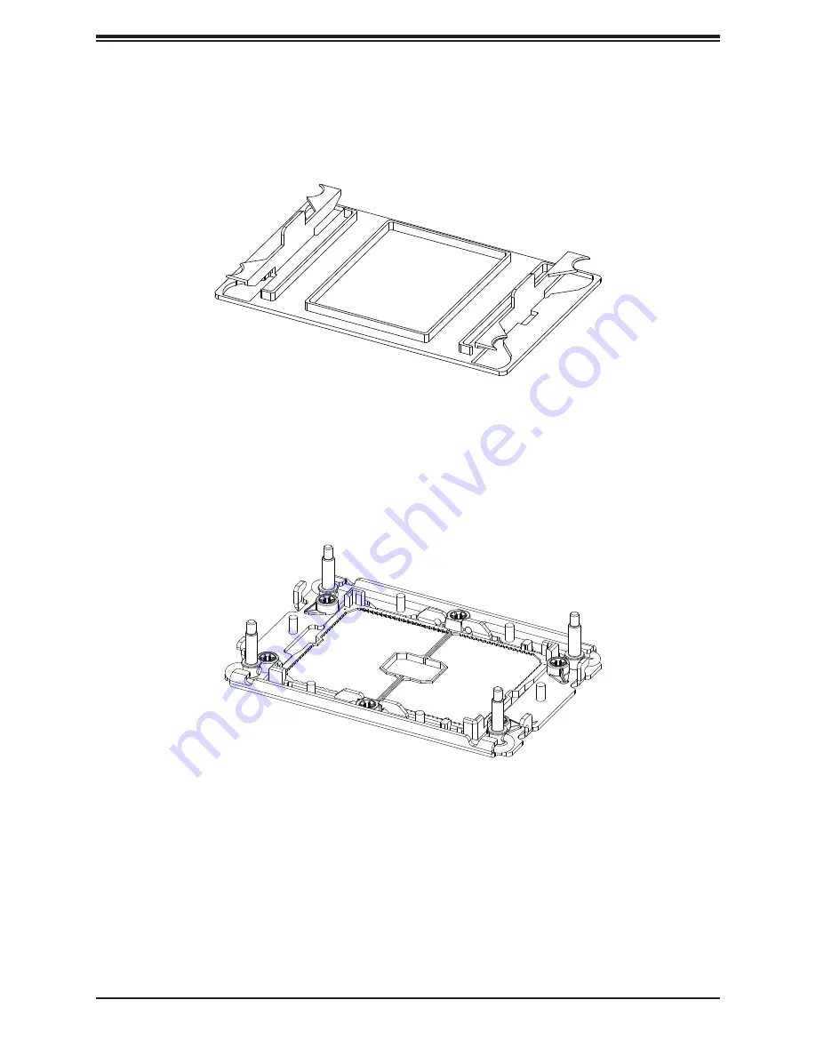
The CPU socket is protected by a plastic protective cover.
Plastic Protective Cover
CPU Socket
Страница 1: ...USER S MANUAL Revision 1 0 SuperWorkstation SYS 730A I...
Страница 2: ...lass A device or in residential environment for Class B device This equipment generates uses and can radiate radio frequency energy and if not installed and used in accordance with the manufacturer s...
Страница 3: ...nd utilities https www supermicro com wdl driver Product safety info http www supermicro com about policies safety_information cfm If you have any questions please contact our support team at support...
Страница 4: ...20 Processor and Heatsink Installation 20 ESD Precautions 20 The 3rd Gen Intel Xeon Scalable Processor 21 Overview of the CPU Socket 24 Overview of the Processor Carrier Assembly 25 Overview of the P...
Страница 5: ...ons 4 1 Power Connections 53 4 2 Headers and Connectors 54 Control Panel 58 4 3 Input Output Ports 61 4 4 Jumpers 64 4 5 LED Indicators 66 Chapter 5 Software 5 1 Microsoft Windows OS Installation 68 5...
Страница 6: ...ST Codes 80 7 5 Crash Dump Using BMC 81 7 6 UEFI BIOS Recovery 82 Overview 82 Recovering the UEFI BIOS Image 82 Recovering the Main BIOS Block with a USB Device 82 7 7 CMOS Clear 87 7 8 Where to Get R...
Страница 7: ...er Micro Computer B V Het Sterrenbeeld 28 5215 ML s Hertogenbosch The Netherlands Tel 31 0 73 6400390 Fax 31 0 73 6416525 Email sales supermicro nl General Information support supermicro nl Technical...
Страница 8: ...6 memory slots and up to 4 TB of Intel Optane PMem 200 Series with speeds of up to 3200 MHz Note PMem 200 Series are supported on 3rd gen Intel Xeon Scalable Platinum Gold and selected Silver processo...
Страница 9: ...or 3D modeling The following views of the system display the main features Front View Figure 1 1 Front View System Features Front Feature Description Lock Front Bezel Lock 5 25 Drive Bays For optional...
Страница 10: ...supply to the system but maintains standby power HDD LED Indicates activity on the storage drives when flashing USB Ports Two front accessible USB 3 2 Gen 1 ports and one USB 3 2 Gen 2 Type C port Au...
Страница 11: ...rear USB 3 2 Gen 1 ports and one rear USB 3 2 Gen 2 port VGA VGA port Audio 7 1 HD Audio ports Expansion Slots Six PCIe expansion slots Power Supply Fan Expansion Slots VGA Port Four USB 3 2 Gen 1 Po...
Страница 12: ...SATA1 I SATA0 I SATA6 I SATA7 LAN 1 2 HD AUDIO P2_NVME0 1 USB7 3 1 LED PWR USB4 3 1 P1_NVME0 1 USB5 6 3 0 USB0 1 2 3 3 0 VGA COM1 CMOS CLEAR TPM PORT80 JTPM1 P1 DIMMB1 P1 DIMMA1 P1 DIMMD1 P1 DIMMC1 P1...
Страница 13: ...Audio port on the I O back panel JD1 Speaker buzzer header use in conjunction with an external speaker buzzer optional JF1 Front Control Panel Header JIPMB1 4 pin BMC External I2 C Header for a BMC c...
Страница 14: ...80 Connector JUSB1 USB0 1 2 3 Back panel USB 3 2 Gen 1 ports JUSBA USB4 Back panel USB 3 2 Gen 2 type A port JUSB31_l1 USB7 Front accessible USB 3 2 Gen 2 header JVGA VGA port on the I O back panel J...
Страница 15: ...LOT 6 PECI 31 VR13HC 1 TMP432 2 RT1 RT2 2666 2933 3200 PVCCIN_CPU1 12V_STBY 2666 2933 3200 PCIe X16 DDR4 CPU2 C1 BMC PCIe X8 G4 CPU2 F1 SPI CPU1 CPU2 A1 UPI SPI 2666 2933 3200 7 1 PHASE 270W PCIe GEN4...
Страница 16: ...ay If any equipment appears damaged file a damage claim with the carrier who delivered it The system should be situated in a clean dust free area that is well ventilated Avoid areas where heat electri...
Страница 17: ...to protect the workstation from power surges voltage spikes and to keep your system operating in case of a power failure Allow the power supply units and components to cool before touching them To mai...
Страница 18: ...numbers given Installation or replacement of most components require that power first be removed from the system Please follow the procedures given in each section 3 1 Removing Power Use the following...
Страница 19: ...of the chassis 3 Lift the left cover from the chassis 4 Remove the three screws securing the right side cover to the chassis 5 Slide the right cover toward the rear of the chassis 6 Lift the right co...
Страница 20: ...installation or socket misalignment can cause serious damage to the processor or CPU socket which may require manufacturer repairs Thermal grease is pre applied on a new heatsink No additional thermal...
Страница 21: ...Maintenance and Component Installation 21 The 3rd Gen Intel Xeon Scalable Processor Cutout CPU Key Pin 1 Processor Top View Cutout CPU Key Pin 1 Processor Top View 1 The 3rd Gen Intel Xeon Scalable P...
Страница 22: ...22 Chapter 3 Maintenance and Component Installation 2 The Processor Carrier Cutout CPU Key Pin 1 Carrier Bottom View Carrier Top View...
Страница 23: ...nk is sold separately and not included as part of the system Exercise extreme care when handling the heatsink Pay attention to the edges of heatsink fins which can be sharp To avoid damaging the heats...
Страница 24: ...24 Chapter 3 Maintenance and Component Installation Overview of the CPU Socket The CPU socket is protected by a plastic protective cover Plastic Protective Cover CPU Socket...
Страница 25: ...processor and a processor carrier Carefully follow the instructions given in the installation section to place a processor into the carrier to create a processor carrier 1 The 3rd Gen Intel Xeon Scala...
Страница 26: ...e Processor Heatsink Module The Processor Heatsink Module PHM contains a heatsink a processor carrier and the 3rd Gen Intel Xeon Scalable Processor 1 Heatsink 2 Processor Carrier 3 The 3rd Gen Intel X...
Страница 27: ...ing down Locate the small gold triangle at the corner of the processor and the corresponding hollowed triangle on the processor carrier as shown in the graphics below Please note that the triangle ind...
Страница 28: ...keys A B on the processor against the CPU keys on the carrier a b as shown in the drawing below 3 Once they are properly aligned carefully place one end of the processor into the latch marked 1 on the...
Страница 29: ...locate the triangle on the CPU and the triangle on the carrier Triangle indicates Pin 1 3 Using Pin 1 as a guide turn the processor carrier assembly over with the gold contacts facing up Locate Pin 1...
Страница 30: ...his motherboard comes with a plastic protective cover installed on the CPU socket Remove it from the socket to install the Processor Heatsink Module PHM Gently pull up one corner of the plastic protec...
Страница 31: ...cket Peek Nut Unlatched latched Rotating Wire A B C D Peek Nut 1 2 3 4 Rotating Wire a b c d Threaded Fastener Rotating Wire 3 Peek Nut A B C D Rotating Wire 1 2 Rotating Wire 4 Threaded Fastener a b...
Страница 32: ...perly aligned with the correspondent threaded fasteners on the CPU socket 2 Once they are aligned gently place the heatsink on top the CPU socket making sure that each peek nut is properly attached to...
Страница 33: ...wdriver tighten all peek nuts in the sequence of A B C and D with even pressure To avoid damaging the processor or socket do not use a force greater than 12 lbf in when tightening the screws 5 Examine...
Страница 34: ...ll power supplies after shutting down the system Then follow the steps below 1 Use a T30 bit screwdriver to loosen the four peek nuts on the heatsink in the sequence of A B C and D A B C D Peek Nut 2...
Страница 35: ...the PHM please follow the steps below 1 Detach four plastic clips marked a b c d on the processor carrier assembly from the four corners of heatsink marked A B C D in the drawings below c a b d A C D...
Страница 36: ...om the processor carrier by following the steps below 1 Unlock the lever from its locking position and push the lever upwards to disengage the processor from the processor carrier as shown in the righ...
Страница 37: ...a Width DIMM Capacity GB Speed MT s Voltage V Slots Per Channel SPC and DIMMs Per Channel DPC 1DPC 1 DIMM Per Chan nel 2DPC 2 DIMM Per Channel 8Gb 16Gb 1 2 V 1 2 V RDIMM SRx8 8GB 16GB 3200 3200 SRx4 1...
Страница 38: ...CPU2 A1 E1 2 CPUs 8 DIMMs CPU1 A1 E1 C1 G1 CPU2 A1 E1 C1 G1 2 CPUs 10 DIMMs CPU1 A1 E1 C1 G1 B1 F1 CPU2 A1 E1 C1 G1 2 CPUs 12 DIMMs CPU1 A1 E1 C1 G1 B1 F1 CPU2 A1 E1 C1 G1 B1 F1 2 CPUs 14 DIMMs CPU1...
Страница 39: ...on 3rd Gen Intel Xeon Scalable Platinum Gold and selected Silver processors PMem may only be supported under certain conditions please contact Supermicro technical support for additional information V...
Страница 40: ...A JSD1 JSD2 JUSB1 JP7 JUSB31_I1 JLAN1 JPCIE6 JAUDIO1 JIPMB1 RAID KEY 1 I SATA5 I SATA4 I SATA3 I SATA2 I SATA1 I SATA0 I SATA6 I SATA7 LAN 1 2 HD AUDIO P2_NVME0 1 USB7 3 1 LED PWR USB4 3 1 P1_NVME0 1...
Страница 41: ...JSPDIF_OUT1 JTPM1 JA1 JRK1 LEDM1 LE4 LE7 JPI2C1 JVGA FAN1 FAN2 FAN5 FAN6 FAN3 FAN4 FAN7 JNCSI JNVME1 JNVME2 JPCIE5 JPCIE4 JPCIE3 JPCIE2 JPCIE1 JF1 JUSBA JSD1 JSD2 JUSB1 JP7 JUSB31_I1 JLAN1 JPCIE6 JAU...
Страница 42: ...JNVI2C JPME1 JPL1 JWD1 JPL2 JD1 JVRM1 JVRM2 JL1 JSPDIF_IN1 JSPDIF_OUT1 JTPM1 JA1 JRK1 LEDM1 LE4 LE7 JPI2C1 JVGA FAN1 FAN2 FAN5 FAN6 FAN3 FAN4 FAN7 JNCSI JNVME1 JNVME2 JPCIE5 JPCIE4 JPCIE3 JPCIE2 JPCIE...
Страница 43: ...ase tab to unlock the PCI slot bracket 4 Pull the release tab upward 5 Remove the screw holding the bracket in place and pull the bracket from the chassis 6 Install your PCI card or other add on card...
Страница 44: ...the motherboard Replacing the Battery Begin by removing power from the system 1 Push aside the small clamp that covers the edge of the battery When the battery is released lift it out of the holder 2...
Страница 45: ...n optional internal hard drive cage Release Tab A HDD Cage B 2 2 1 3 Figure 3 6 Rotating the Internal Hard Drive Cage Rotating the Hard Drive Cage 1 Begin by removing power from the system as describe...
Страница 46: ...ing 3 5 Hard Drives 1 Begin by removing power from the system as described in Section 3 1 and remove the side cover as described in Section 3 2 2 Rotate the hard drive cage outward 3 Disconnect all of...
Страница 47: ...the drive from the carrier 7 Insert a new drive into the carrier and push the sides of the carrier together 8 Insert the carrier into the cage Slide the carrier towards the back of the cage until it c...
Страница 48: ...d in Section 3 1 and remove the side cover as described in Section 3 2 2 Loosen the thumbscrew securing the 2 5 hard drive cage to the chassis 3 Disconnect all cables from the hard drive 4 Slide the 2...
Страница 49: ...drive cage sliding it towards the back of the the hard drive cage until it clicks into a locked position 9 Slide the 2 5 hard drive cage back into the chassis and tighten the thumb screw to secure the...
Страница 50: ...e rear of the chassis and through the mounting holes in the rear fan 3 Pull the rubber pins through the mounting holes of the fan to secure the fan to the chassis 4 Connect the fan cable to the mother...
Страница 51: ...s described in Section 3 2 2 Insert the four rubber pins through the front fan bracket and into the mounting holes in the front fan 3 Pull the rubber pins through the mounting holes of the system fan...
Страница 52: ...the rear of the chassis Set these screws aside for later use 3 Disconnect the power supply from the motherboard connections 4 Gently lift the power supply out of the chassis 5 Replace the failed power...
Страница 53: ...e 24 pin power supply connector JPWR3 meets the ATX SSI EPS 12V specification You must also connect the 8 pin JPWR1 JPWR2 JPWR4 processor power connector to the power supply Refer to the next page for...
Страница 54: ...2 2 5A 12V Red 3 Tachometer 4 PWM_Control SGPIO Headers There are three Serial Link General Purpose Input Output I SGPIO1 and I SGPIO2 headers located on the motherboard I SGPIO is for SATA use Refer...
Страница 55: ...wing link for more information on the TPM http www supermicro com manuals other TPM pdf Power SMB I2 C Header The Power System Management Bus I2 C connector JPI2C1 monitors the power supply fan and sy...
Страница 56: ...for pin definitions NVMe SMBus Header Pin Definitions Pin Definition 1 Data 2 Ground 3 Clock 4 VCCIO Chassis Intrusion A Chassis Intrusion header is located at JL1 on the motherboard Attach the appro...
Страница 57: ...JM2_1 and JM2_2 M 2 allows for a variety of card sizes increased functionality and spatial efficiency The M 2 socket on the motherboard supports PCIe 4 0 x4 32 Gb s SSD cards in the 2280 and 22110 fo...
Страница 58: ...are designed specifically for use with Supermicro chassis See the figure below for the descriptions of the front control panel buttons and LED indicators Power Button Blue LED_Cathode_UID NIC1 Activi...
Страница 59: ...ecking BMC BIOS Blinking 4HZ Not supported Recovering Updating BMC Blinking 4HZ BMC 2 Blinks 4Hz 1 Pause 2Hz on on off off BIOS BMC Blinking 10Hz Not supported Flash Not Detected or Golden Image Check...
Страница 60: ...ins will power on off the system or display BMC BIOS status Refer to the tables below for more information Power Button Pin Definitions Pin 1 Pin 2 of JF1 Status Event Green solid on System power on B...
Страница 61: ...JD1 JVRM1 JVRM2 JL1 JSPDIF_IN1 JSPDIF_OUT1 JTPM1 JA1 JRK1 LEDM1 LE4 LE7 JPI2C1 JVGA FAN1 FAN2 FAN5 FAN6 FAN3 FAN4 FAN7 JNCSI JNVME1 JNVME2 JPCIE5 JPCIE4 JPCIE3 JPCIE2 JPCIE1 JF1 JUSBA JSD1 JSD2 JUSB1...
Страница 62: ...ropriate software from our website to enable this function Front Accessible Audio Header A 10 pin audio header located at JA1 allows you to use the onboard sound for audio playback Connect an audio ca...
Страница 63: ...LAN connections on the X12DAi N6 All of these ports accept RJ45 cables Please refer to the LED Indicator section for LAN LED information LAN Port Pin Definition Pin Definition Pin Definition 1 TD0 11...
Страница 64: ...Pins Jumper Setting 3 2 1 3 2 1 CMOS Clear JBT1 is used to clear CMOS which will also clear any passwords Instead of pins this jumper consists of contact pads to prevent accidentally clearing the con...
Страница 65: ...t also be enabled in the BIOS Watchdog Jumper Settings Jumper Setting Definition Pins 1 2 Reset Pins 2 3 NMI Open Disabled Management Engine ME Recovery Use jumper JPME1 to select ME Firmware Recovery...
Страница 66: ...Color Definition Yellow Amber 1Gbps M 2 LED Two M 2 LEDs are located at LE4 and LE7 on the motherboard When the LED is blinking M 2 functions normally Refer to the table below for more information M...
Страница 67: ...tbeat LED A BMC Heartbeat LED is located at LEDM1 on the motherboard When LEDM1 is blinking the BMC is functioning normally Refer to the table below for more information BMC Heartbeat LED Indicator LE...
Страница 68: ...upermicro com support manuals Installing the OS 1 Create a method to access the MS Windows installation ISO file That might be a DVD perhaps using an external USB SATA DVD drive or a USB flash drive o...
Страница 69: ...iver browse the USB flash drive for the proper driver files For RAID choose the SATA sSATA RAID driver indicated then choose the storage drive on which you want to install it For non RAID choose the S...
Страница 70: ...other option is to go to the Supermicro website at http www supermicro com products Find the product page for your motherboard and Download the Latest Drivers and Utilities Insert the flash drive or d...
Страница 71: ...Network Management Protocol SNMP SuperDoctor 5 comes in local and remote management versions and can be used with Nagios to maximize your system monitoring needs With SuperDoctor 5 Management Server...
Страница 72: ...C For general documentation and information on BMC visit our website at www supermicro com en solutions management software bmc resources BMC ADMIN User Password For security each system is assigned a...
Страница 73: ...e installed in the chassis 5 25 bay to support hot swappable drives An additional internal 2 5 hard drive cage can be installed beneath the rotating drive cage Both the mobile rack and the hard drive...
Страница 74: ...other service extensions Direct Links for the SYS 730A I System SYS 730A I specifications page X12DAi N6 motherboard page for links to the Quick Reference Guide User Manual validated storage drives et...
Страница 75: ...ro Phone and Addresses Direct Links continued 7 2 BMC Interface The system supports the Baseboard Management Controller BMC Interface BMC is used to provide remote access monitoring and management The...
Страница 76: ...CENSE JM2_2 MH18 MH17 JM2_1 MH16 MH15 HEARTBEAT BMC FANA JBT1 T SGPIO2 T SGPIO1 BT1 JPWR3 J37 SATA4 SATA6 SATA5 SATA8 SATA7 SATA1 SATA3 SATA2 JPWR2 JPWR1 JPWR4 JPRG1 JNVI2C JPME1 JPL1 JWD1 JPL2 JD1 JV...
Страница 77: ...manufacturer Check to verify that it still supplies 3VDC If it does not replace it with a new one Warning To avoid possible explosion do not install the battery upside down 14 Verify that all jumpers...
Страница 78: ...e steps do not fix the setup configuration problem contact your vendor for repairs When the System Becomes Unstable If the system becomes unstable during or after OS installation check the following 1...
Страница 79: ...ve all unnecessary components starting with add on cards first and use the minimum configuration but with a CPU and a memory module installed to identify the trouble areas Refer to the steps listed in...
Страница 80: ...nding beep codes encountered by users BIOS Error Beep POST Codes Beep Code Error Message Description 1 short Refresh Circuits have been reset Ready to power up 5 short 1 long Memory error No memory de...
Страница 81: ...download a crash dump of status information using BMC The BMC manual is available at https www supermicro com en solutions management software bmc resources Check BMC Error Log 1 Access the BMC web in...
Страница 82: ...ed When the system power is turned on the recovery block codes execute first Once this process is complete the main BIOS code will continue with system initialization and the remaining POST Power On S...
Страница 83: ...e BIOS binary image into a USB flash device and rename it Super ROM for the BIOS recovery use Note 2 Before recovering the main BIOS image confirm that the Super ROM binary image file you download is...
Страница 84: ...shown above displays use the arrow keys to select the item Proceed with flash update and press the Enter key You will see the BIOS recovery progress as shown in the screen below Note Do not interrupt...
Страница 85: ...EFI Shell prompt appears type fs to change the device directory path Go to the directory that contains the BIOS package you extracted earlier from Step 6 Enter flash nsh BIOSname at the prompt to star...
Страница 86: ...complete When you see the screen above unplug the AC power cable from the power supply clear CMOS and plug the AC power cable in the power supply again to power on the system 10 Press Del continuously...
Страница 87: ...mpletely 2 Remove chassis side cover to access the motherboard 3 Remove the onboard battery from the motherboard 4 Short the CMOS pads with a metal object such as a small screwdriver for at least four...
Страница 88: ...boot block code 3 If you still cannot resolve the problem include the following information when contacting us for technical support System motherboard and chassis model numbers and PCB revision numbe...
Страница 89: ...lure due to the alteration misuse abuse or improper maintenance of products During the warranty period contact your distributor first for any product problems Vendor Support Filing System For issues r...
Страница 90: ...sistance Only certified technicians should attempt to install or configure components Read this appendix in its entirety before installing or configuring components in the Supermicro chassis These war...
Страница 91: ...idere los riesgos de la corriente el ctrica y familiar cese con los procedimientos est ndar de prevenci n de accidentes Al final de cada advertencia encontrar el n mero que le ayudar a encontrar el te...
Страница 92: ...ient u zich bewust te zijn van de bij een elektrische installatie betrokken risico s en dient u op de hoogte te zijn van de standaard procedures om ongelukken te voorkomen Gebruik de nummers aan het e...
Страница 93: ...n Attention Avant de brancher le syst me sur la source d alimentation consulter les directives d installation Circuit Breaker Waarschuwing Raadpleeg de installatie instructies voordat u het systeem o...
Страница 94: ...e la protection contre les courts circuits surtension ce produit d pend de l installation lectrique du local V rifiez que le courant nominal du dispositif de protection n est pas sup rieur 250 V 20 A...
Страница 95: ...zu entfernen Advertencia El sistema debe ser disconnected de todas las fuentes de energ a y del cable el ctrico quitado de los m dulos de fuente de alimentaci n antes de tener acceso el interior del c...
Страница 96: ...aangesloten op de voeding en van de behuizing te verwijderen Equipment Installation Warning Only trained and qualified personnel should be allowed to install replace or service this equipment Warnung...
Страница 97: ...Il est vivement recommand de confier l installation le remplacement et la maintenance de ces quipements des personnels qualifi s et exp riment s Warning This unit is intended for installation in rest...
Страница 98: ...a de estas reas mediante la utilizaci n de una herramienta especial cerradura con llave u otro medio de seguridad Attention Cet appareil doit tre install e dans des zones d acc s r serv s L acc s une...
Страница 99: ...e ou quivalent recommand e par le fabricant Jeter les piles usag es conform ment aux instructions du fabricant Advertencia Existe peligro de explosi n si la bater a se reemplaza de manera incorrecta R...
Страница 100: ...evolen wordt Gebruikte batterijen dienen overeenkomstig fabrieksvoorschriften afgevoerd te worden Redundant Power Supplies Warning This unit might have more than one power supply connection All connec...
Страница 101: ...te maken Advertencia Puede que esta unidad tenga m s de una conexi n para fuentes de alimentaci n Para cortar por completo el suministro de energ a deben desconectarse todas las conexiones Attention C...
Страница 102: ...tencia Cuando el sistema est en funcionamiento el voltaje del plano trasero es peligroso Tenga cuidado cuando lo revise Attention Lorsque le syst me est en fonctionnement des tensions lectriques circu...
Страница 103: ...con las normas de electricidad locales y nacionales Backplane Waarschuwing Een gevaarlijke spanning of energie is aanwezig op de backplane wanneer het systeem in gebruik is Voorzichtigheid is geboden...
Страница 104: ...elektriciteitsvoorschriften Warnung Die Entsorgung dieses Produkts sollte gem allen Bestimmungen und Gesetzen des Landes erfolgen Warning Ultimate disposal of this product should be handled according...
Страница 105: ...lage de ce produit sont g n ralement soumis des lois et ou directives de respect de l environnement Renseignez vous aupr s de l organisme comp tent Hot Swap Fan Warning Warning Hazardous moving parts...
Страница 106: ...rnilladores y todos los objetos lejos de las aberturas del ventilador Attention Pieces mobiles dangereuses Se tenir a l ecart des lames du ventilateur Il est possible que les ventilateurs soient toujo...
Страница 107: ...r CAS zertifizierten Kabeln mit UL CSA gekennzeichnet an Ger ten oder Produkten die nicht mit Supermicro gekennzeichnet sind AC AC UL CSA UL CSA Supermicro Supermicro UL CSA UL CSA Supermicro UL CSA U...
Страница 108: ...code pour tous les autres appareils lectriques sauf les produits d sign s par Supermicro seulement AC AC UL CSA UL CSA Supermicro UL CSA UL CSA Supermicro Advertencia Cuando instale el producto utilic...
Страница 109: ...uitmethode deze moet altijd voldoen aan de lokale voorschriften en veiligheidsnormen inclusief de juiste kabeldikte en stekker Het gebruik van niet geschikte Kabels en of Adapters kan een storing of b...
Страница 110: ...16 memory slots and up to 4 TB of Intel Optane PMem 200 Series with speeds of up to 3200 MHz Note PMem 200 Series are supported on 3rd gen Intel Xeon Scalable Platinum Gold and selected Silver proces...
Страница 111: ...FCC Class A ICES CE VCCI RCM NRTL CB Applied Directives Standards EMC EMI 2014 30 EU EMC Directive FCC Part 15 ICE 003 VCC 32 1 AS NZS CISPR 32 EN55032 EN55035 CISPR 24 EN 61000 3 2 EN 61000 3 3 EN 6...