


6-2
S
UPER
S
ERVER 6016T-URF4+/6016T-NTRF4+ User's Manual
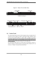
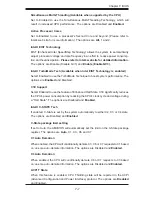
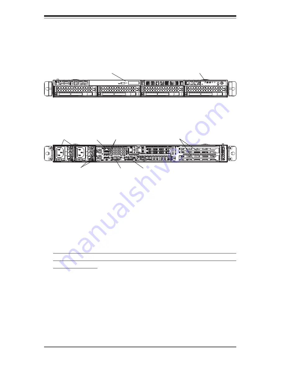
Figure 6-1. Chassis: Front and Rear Views
6-2 Control
Panel
The control panel (located on the front of the chassis) must be connected to the JF1
connector on the serverboard to provide you with system status indications. These
wires have been bundled together as a ribbon cable to simplify the connection.
Connect the cable from JF1 on the serverboard to the appropriate header on the
Control Panel PCB (printed circuit board). Make sure the red wire plugs into pin 1
on both connectors. Pull all excess cabling out of the airfl ow path.
The control panel LEDs inform you of system status. See "Chapter 3: System In-
terface" for details on the LEDs and the control panel buttons. Details on JF1 can
be found in "Chapter 5: Advanced Serverboard Setup."
Control Panel
Slim DVD-ROM
SAS/SATA Drive Bays (4)
PCI Expansion Slots (w/riser card)
Mouse/Keyboard Ports
USB Ports
COM1 Port
Power Supplies
VGA Port
IPMI LAN
Содержание SUPERSERVER 6016T-NTRF4+
Страница 1: ...SUPERSERVER 6016T URF4 6016T NTRF4 SUPER USER S MANUAL 1 0a ...
Страница 5: ...v Preface Notes ...
Страница 21: ...Chapter 2 Server Installation 2 7 Figure 2 3 Installing the Server into a Rack ...
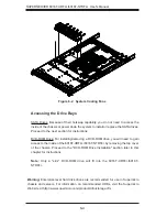
Страница 23: ...Chapter 2 Server Installation 2 9 Figure 2 4 Accessing the Inside of the System ...
Страница 28: ...3 4 SUPERSERVER 6016T URF4 6016T NTRF4 User s Manual Notes ...
Страница 48: ...4 20 SUPERSERVER 6016T URF4 6016T NTRF4 User s Manual Notes ...
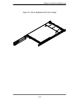
Страница 87: ...Chapter 6 Advanced Chassis Setup 6 9 Figure 6 5 Removing Replacing the Power Supply ...
Страница 88: ...6 10 SUPERSERVER 6016T URF4 6016T NTRF4 User s Manual Notes ...
Страница 116: ...7 28 SUPERSERVER 6016T URF4 6016T NTRF4 User s Manual Notes ...
Страница 118: ...A 2 SUPERSERVER 6016T URF4 6016T NTRF4 User s Manual Notes ...


