


C-3
Appendix C: Backplane Specifications
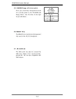
#3. I
2
C Connector
The I
2
C Connector, designated JP44, is used
to monitor HDD activity and status. See the
table on the right for pin definitions.
I
2
C Connector
Pin Definitions
(JP44)
Pin# Definition
1
Data
2
Ground
3
Clock
4
No Connection
Backplane
Main Power
4-Pin Connector
(JP10)
Pin# Definition
1
+12V
2 and 3
Ground
4
+5V
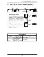
C-5 Front Connector and Pin Definitions
#1. Backplane Main Power Connector
The 4-pin connector, designated JP10,
provides power to the backplane. See the
table on the right for pin definitions.
#2. Sideband Connector
The sideband connector is designated
JP51. For SES-2 to work properly, you
must connect an 8-pin sideband cable to
JP51. See the table to the right for pin
definitions.
Sideband Connector
(JP51)
Pin # Definition
Pin # Definition
2
Backplane
Addressing
(SB5)
1
Controller
ID (SB6)
4
Reset (SB4)
3
GND (SB2)
6
GND (SB3)
5
SDA (SB1)
8
Backplane
ID (SB7)
7
SCL (SB0)
10
No Connec-
tion
9
No Connec-
tion
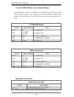
SAS Activity LED Header
Pin Definitions (JP26)
Pin # Definition
Pin # Definition
1
ACT IN#0
6
ACT IN#4
2
ACT IN#1
7
ACT IN#5
3
ACT IN#2
8
ACT IN#6
4
ACT IN#3
9
ACT IN#7
5
Ground
10
Empty
#4. Activity LED Header
The activity LED header, designated
JP26, is used to indicate the activity
status of each hard drive. The Activity
LED Header is located on the rear of the
front panel. For the Activity LED Header
to work properly, connect using a 10-pin
LED cable.
Содержание SC825MS-R700LPB
Страница 1: ...SC825M Chassis Series SUPER USER S MANUAL 1 0a SC825MTQ R700LPB SC825MS R700LPB SC825MTQ R700UB ...
Страница 11: ...SC825M Chassis Manual 1 4 Notes ...
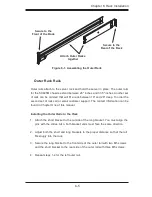
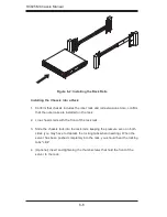
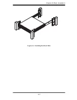
Страница 49: ...6 7 Chapter 6 Rack Installation Figure 6 3 Installing the Rack Rails ...
Страница 50: ...SC825M Chassis Manual 6 8 Notes ...
Страница 56: ...SC825M Chassis Manual B 2 Notes ...


