B-9
Appendix B: BPN-SAS-825TQ Backplane Specifications
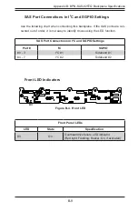
SAS Port Connections in I
2
C and SGPIO Settings
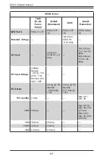
Use the following chart when connecting this backplane. If the SAS ports are con-
nected out of order, it is not easy to identify drives using the LED function.
SAS Port Connections in I
2
C and SGPIO Settings
Port #
I
2
C
SGPIO
# 0 - 3
I
2
C #1
Sideband #1
# 4 - 7
I
2
C #2
Sideband #2
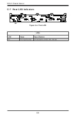
Front Panel LEDs
LED
State
Specification
D3
On
Overheat/drive failure LED indicator.
(Red light: Flashing. Buzzer: On, if activated)
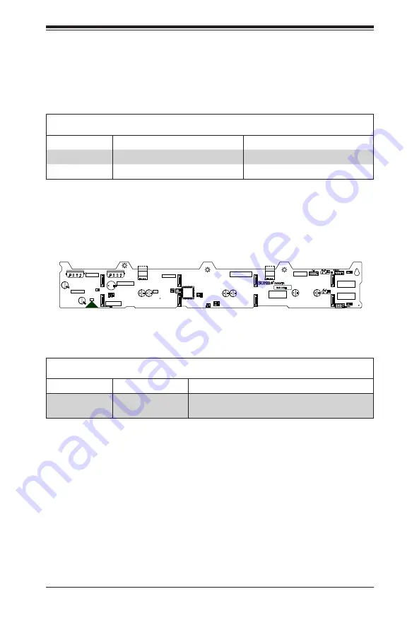
Front LED Indicators
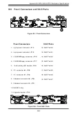
Figure B-4. Front LED
1
1
16
32
48
BAR CODE
REV 2.0
SAS825TQ
1
GND
GND
+12V
+5V
GND
GND
+12V
+5V
#2
I C
#1
ACT_IN
JP29:9072 RESET
I C
SIDEBAND #2
SIDEBAND #1
2
2
+ +
+ +
+ +
+ +
+
+
+
+
+
+
1
1
1
16
32
48
GND
GND
+12V
+5V
GND
GND
+12V
+5V
+
+
+
BAR CODE
+
+
+
REV 2.0
SAS825TQ
#2
2
I C
#1
ACT_IN
JP29:9072 RESET
2
I C
SIDEBAND #2
SIDEBAND #1
+ +
+ +
+ +
+ +
D3
Содержание SC825 Series
Страница 8: ...8 SC825 Chassis Manual Notes ...
Страница 14: ...SC825 Chassis Manual 1 6 Notes ...
Страница 62: ...SC825 Chassis Manual 5 22 Figure 5 19 Placing a System Fan ...
Страница 68: ...SC825 Chassis Manual 5 28 Notes ...

