background image

7

Chapter 1: Introduction

Chapter 1  


Introduction

1.1 Overview

The Supermicro SC506, is an all-purpose chassis for many different applications. It is an 
excellent chassis platform for data centers, government labs, or business enterprises, for 
cloud and virtualization, simulation, automation, hosting and storage.
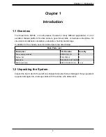
In addition to the chassis, several included parts are listed below.

Main Parts List

Description

Part Number

Quantity

Power supply modules

PWS-301R-1R

2

System Fan

FAN-0065L4

3

Backplane

BPN-SAS3-826TQ-B2B 1

Rail kit (optional)

MCP-290-50404-ON

1 set

1.2 Unpacking the System

Inspect the box in which the server was shipped and note if it was damaged. If any equipment 

appears damaged, file a damage claim with the carrier who delivered it.

Содержание SC506 Series

Страница 1: ...SC506 Chassis Series USER S MANUAL Revision 1 0...

Страница 2: ...nment for Class A device or in residential environment for Class B device This equipment generates uses and can radiate radio frequency energy and if not installed and used in accordance with the manu...

Страница 3: ...the user s manual for your server Supermicro product manuals http www supermicro com support manuals Product drivers and utilities https www supermicro com wld Product safety info http www supermicro...

Страница 4: ...cautions 10 General Server Precautions 11 Rack Mounting Considerations 11 Ambient Operating Temperature 11 Reduced Airflow 11 Mechanical Loading 11 Circuit Overloading 12 Reliable Ground 12 2 4 Rack M...

Страница 5: ...oard Installation 22 Installing the Motherboard 22 Appendix A Cables Screws and Other Accessories A 1 Overview 23 A 2 Cables Included with the SC506 Chassis 23 A 3 Optional Accessories 23 Hard Drive B...

Страница 6: ...r Micro Computer B V Het Sterrenbeeld 28 5215 ML s Hertogenbosch The Netherlands Tel 31 0 73 6400390 Fax 31 0 73 6416525 Email sales supermicro nl General Information support supermicro nl Technical S...

Страница 7: ...ion automation hosting and storage In addition to the chassis several included parts are listed below Main Parts List Description Part Number Quantity Power supply modules PWS 301R 1R 2 System Fan FAN...

Страница 8: ...ystem is operating normally 4 HDD LED Indicates hard disk drive activity 5 NIC LED Indicates network activity on LAN1 when flashing 6 NIC LED Indicates network activity on LAN2 when flashing 7 Informa...

Страница 9: ...ssis Front Chassis Features Item Feature Description 1 Control Panel Described in previous section 2 Drives Two 2 5 SAS3 SATA hot swap storage drive bays 1 2 Rear Chassis Features Item Feature Descrip...

Страница 10: ...e Rack and Server Precautions in the next section 2 3 Preparing for Setup The box your chassis was shipped in should include four mounting screws which you will need if you intend to install the syste...

Страница 11: ...ltage spikes and to keep your system operating in case of a power failure Allow the hard drives and power supply modules to cool before touching them Always keep the rack s front door all panels and a...

Страница 12: ...uld be given to power supply connections other than the di rect connections to the branch circuit for example the use of power strips and other devices To prevent bodily injury when mounting or servic...

Страница 13: ...dard Rack Installation Procedure 1 Confirm that chassis includes the four mounting screws required to mount the chassis into a rack 2 Align the thru holes of the chassis with the thru holes of the rac...

Страница 14: ...balance the weight between front and back If a bezel is included on your chassis remove it Then attach the two front brackets to each side of the chassis then the two rear brackets positioned with jus...

Страница 15: ...rail kit optional MCP 290 50404 0N Installing the Chassis on Fixed Rails into a Standard Rack 1 Adjust the rails to the appropriate length according to the distance between the front and back of the...

Страница 16: ...ugh each rear bracket to secure the rails to the rack Figure 6 5 Rails Attached to the Chassis 1 Attach the rails to the chassis using three screws through the holes in each front bracket to secure a...

Страница 17: ...7 Chapter 6 Rack Installation Note Figures are for illustrative purposes only Servers should always be installed in racks from the bottom up Figure 6 8 Installing the Server on Fixed Rails into a Rack...

Страница 18: ...re that power first be removed from the system Please follow the procedures given in each section 3 1 Removing Power Use the following procedure to ensure that power has been removed from the system T...

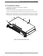
Страница 19: ...Top Cover 1 Remove the screw from the left right and top sides of the chassis as shown 2 Push the cover towards the back and pull the top cover straight up Set aside screws Caution Except for short p...

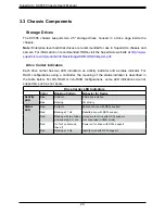
Страница 20: ...ndicator For RAID configurations using a controller the meaning of the status indicator is described in the table below For OS RAID or non RAID configurations some LED indications are not supported su...

Страница 21: ...talling a 2 5 Hard Drive 1 Remove the chassis cover as described in Chapter 3 2 2 Remove the left chassis handle as shown below 3 Insert and secure the hard drive s to the hard drive cage with screws...

Страница 22: ...power is on and examine the fans to determine which one has failed 2 Remove the failed fan s power cable from the motherboard 3 Remove the fan housing screws from underneath the chassis 4 Lift the fa...

Страница 23: ...100 120v or 180 240v An amber light will be illuminated on the power supply when the power is off An illuminated green light indicates that the power supply is operating Replacing the Power Supply 1 U...

Страница 24: ...TX motherboards Refer to the Supermicro Web site or contact Supermicro for assistance 1 Power down the server disconnect the power cord from the power supply and remove the cover 2 Compare the mountin...

Страница 25: ...ith the SC506 Chassis SC506 200B Part Type Length Description CBL PWEX 1097 15 Ribbon 6 16 pin to 16 pin ribbon cable for control panel CBL PWEX 1098F 10 Ribbon 4 16 pin to 16 pin ribbon cable control...

Страница 26: ...20 cm 20 pin CBL 0059 7 9 20 cm 8 pin CBL 0062 7 9 20 cm 4 pin CBL0060 7 9 20 cm Front Panel to the Motherboard The SC506 chassis includes a cable to connect the chassis front panel to the motherboard...

Страница 27: ...ad M4 x 4 mm 0 157 RAIL Round head M4 x 4 mm 0 157 Flat head M5 x 12 mm 0 472 Washer for M5 DVD ROM CD ROM and FLOPPY DRIVE Flat head 6 32 x 5 mm 0 197 Pan head 6 32 x 5 mm 0 197 Round head M3 x 5 mm...

Страница 28: ...y Specifications This appendix lists power supply specifications for your chassis system 200W MFR Part PWS 203 1H Rated AC Voltage 100 240V 50 60Hz 4 2 Amps 5V standby 2 Amps 12V 16 Amps 5V 8 Amps 3 3...

Страница 29: ...orm be reasonably expected to result in significant injury or loss of life or catastrophic property damage Accordingly Supermicro disclaims any and all liability and should buyer use or sell such prod...

Отзывы: