Supermicro SC113M Series Скачать руководство пользователя страница 50

4-15

Chapter 4 Chassis Setup and Maintenance

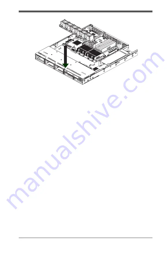
Figure 4-13. Installing the Fan Tray into the Chassis

The SC113M chassis includes four pre-installed fans. Two additional open slots are 

available so that up to two more fans may be added.

Replacing a System Fan

1.  If necessary, open the chassis while the power is running to determine which 

fan has failed. Never run the server for an extended period of time with the 

chassis open.

2.  Power down the system and remove the power cord from the rear of the 

power supply as described in Section 4-2. Open the chassis cover as de-

scribed in Section 4-3.

3.  Remove the failed fan's power cord from the serverboard.

4.  Unscrew the fan tray from the chassis and push the failed fan from the up 

from the bottom of the tray. 

5.  Place the new fan into the vacant space in the housing while making sure the 

arrows on the top of the fan (indicating air direction) point in the same direc-

tion as the arrows on the other fans.

6.  Reconnect the fan wires to the exact same chassis fan headers as the previ-

ous fan.

7.  Power up the system and check that the fan is working properly before re-

placing the chassis cover.

Содержание SC113M Series

Страница 1: ...SC113M CHASSIS SERIES USER S MANUAL 1 1 SC113MFAC2 605CB SC113MTQ 563CB SC113MTQ 330CB SC113MFAC2 R606CB SC113MTQ 600CB SC113MTQ R400CB...

Страница 2: ...DWARE SOFTWARE OR DATA STORED OR USED WITH THE PRODUCT INCLUDING THE COSTS OF REPAIRING REPLACING INTEGRATING INSTALLING OR RECOVERING SUCH HARDWARE SOFTWARE OR DATA Any disputes arising between manuf...

Страница 3: ...performance into an astonishingly short 20 deep chassis featuring advanced airflow thermal design for space limited applications With its short depth it efficiently packages eight hot swappable 2 5 S...

Страница 4: ...nts Refer here for details on this chassis model including the fans bays airflow shields and other components Chapter 4 System Interface This chapter provides details on the system interface which inc...

Страница 5: ...113M system Refer to our website for additional details at www supermicro com Appendix C BPN SAS 113TQ Backplane Specifications This chapter provides information on the BPN SAS 113TQ backplane For add...

Страница 6: ...10 Redundant Power Supplies 2 12 Backplane Voltage 2 13 Comply with Local and National Electrical Codes 2 14 Product Disposal 2 15 Hot Swap Fan Warning 2 16 Power Cable and AC Adapter 2 18 Chapter 3 S...

Страница 7: ...ral Server Precautions 5 2 Rack Mounting Considerations Ambient Operating Temperature Reduced Airflow Mechanical Loading Circuit Overloading Reliable Ground Rack Mounting Considerations 5 3 Ambient Op...

Страница 8: ...y and one slim DVD ROM drive 1 2 Shipping List Chapter 1 Introduction 1 1 SC113M Model HDD PCI Slots Power Supply SC113MFAC2 R606CB 8x 2 5 hot swap SAS SATA 1x FH 600W Redundant SC113MFAC2 605CB 8x 2...

Страница 9: ...e Address Super Micro Computer B V Het Sterrenbeeld 28 5215 ML s Hertogenbosch The Netherlands Tel 31 0 73 6400390 Fax 31 0 73 6416525 Email sales supermicro nl General Information support supermicro...

Страница 10: ...ust be mailed when service is complete For faster service RMA authorizations may be requested online http www super micro com support rma Whenever possible repack the chassis in the original Supermicr...

Страница 11: ...SC113M Chassis Manual 1 4 Notes...

Страница 12: ...nt for assistance Only certified technicians should attempt to install or configure components Read this appendix in its entirety before installing or configuring components in the Supermicro chassis...

Страница 13: ...e los riesgos de la corriente el ctrica y familiar cese con los procedimientos est ndar de prevenci n de accidentes Al final de cada advertencia encontrar el n mero que le ayudar a encontrar el texto...

Страница 14: ...l kan veroorzaken Voordat u aan enige apparatuur gaat werken dient u zich bewust te zijn van de bij een elektrische installatie betrokken risico s en dient u op de hoogte te zijn van de standaard proc...

Страница 15: ...s Systems an die Stromquelle die Installationsanweisungen lesen Advertencia Lea las instrucciones de instalaci n antes de conectar el sistema a la red de alimentaci n Attention Avant de brancher le sy...

Страница 16: ...ert ist Stellen Sie sicher dass der Nennwert der Schutzvorrichtung nicht mehr als 250 V 20 A betr gt Advertencia Este equipo utiliza el sistema de protecci n contra cortocircuitos o sobrecorrientes de...

Страница 17: ...Systemsbestandteile anzubringen oder zu entfernen Warning The system must be disconnected from all sources of power and the power cord removed from the power supply module s before accessing the chass...

Страница 18: ...nentes de sistema Attention Le syst me doit tre d branch de toutes les sources de puissance ainsi que de son cordon d alimentation secteur avant d acc der l int rieur du chassis pour installer ou enle...

Страница 19: ...s Installieren Ersetzen oder Bedienen dieser Ausr stung sollte nur geschultem qualifiziertem Personal gestattet werden Advertencia Solamente el personal calificado debe instalar reemplazar o utilizar...

Страница 20: ...stallation in Bereichen mit beschr nktem Zutritt vorgesehen Der Zutritt zu derartigen Bereichen ist nur mit einem Spezialwerkzeug Schloss und Schl ssel oder einer sonstigen Sicherheitsvorkehrung m gli...

Страница 21: ...quivalent type recommended by the manufacturer Dispose of used batteries according to the manufacturer s instructions Waarschuwing Dit apparaat is bedoeld voor installatie in gebieden met een beperkte...

Страница 22: ...ecommand e par le fabricant Jeter les piles usag es conform ment aux instructions du fabricant Advertencia Existe peligro de explosi n si la bater a se reemplaza de manera incorrecta Reemplazar la bat...

Страница 23: ...entes de alimentaci n Para cortar por completo el suministro de energ a deben desconectarse todas las conexiones Attention Cette unit peut avoir plus d une connexion d alimentation Pour supprimer tout...

Страница 24: ...ero es peligroso Tenga cuidado cuando lo revise Attention Lorsque le syst me est en fonctionnement des tensions lectriques circulent sur le fond de panier Prendre des pr cautions lors de la maintenanc...

Страница 25: ...l codes Warnung Die Installation der Ger te muss den Sicherheitsstandards entsprechen Advertencia La instalacion del equipo debe cumplir con las normas de electricidad locales y nacionales Backplane W...

Страница 26: ...re install conform ment aux normes lectriques nationales et locales Waarschuwing Bij installatie van de apparatuur moet worden voldaan aan de lokale en nationale elektriciteitsvoorschriften Warnung Di...

Страница 27: ...ing parts Keep away from moving fan blades The fans might still be turning when you remove the fan assembly from the chassis Keep fingers screwdrivers and other objects away from the openings in the f...

Страница 28: ...s destornilladores y todos los objetos lejos de las aberturas del ventilador Attention Pieces mobiles dangereuses Se tenir a l ecart des lames du ventilateur Il est possible que les ventilateurs soien...

Страница 29: ...for any other electrical devices than products designated by Supermicro only Power Cable and AC Adapter Warnung Nutzen Sie beim Installieren des Produkts ausschlie lich die von uns zur Verf gung gest...

Страница 30: ...ros dispositivos el ctricos que los productos designados nicamente por Supermicro Attention Attention Lors de l installation du produit utilisez les cables de connection fournis ou d sign ou achetez d...

Страница 31: ...ethode deze moet altijd voldoen aan de lokale voorschriften en veiligheidsnormen inclusief de juiste kabeldikte en stekker Het gebruik van niet geschikte Kabels en of Adapters kan een storing of brand...

Страница 32: ...you constantly informed of the overall status of the system as well as the activity and health of specific components Most SC113M models are two buttons on the control panel a reset button an on off s...

Страница 33: ...eset button and a power on off button Unit Identification LED The Unit Identification LED is used to indicate fan failure power failure overheat condition or to identify the unit within a large rack i...

Страница 34: ...king red 0 25Hz Power failure check for a non operational power supply Solid blue Local UID has been activated Use this function to locate the server in a rack mount environment Blinking blue 300 msec...

Страница 35: ...drive carrier has a green LED When illuminated this green LED on the front of the SATA drive carrier indicates drive activity A connection to the SATA backplane enables this LED to blink on and off w...

Страница 36: ...ng components or performing maintenance the chassis must be powered off and completely disconnected from any power source Removing Power From the Chassis 1 Power down the system using the on screen pr...

Страница 37: ...ower supply as described in Section 4 2 2 Slide the cover toward the rear of the chassis 3 Lift the cover up and off the chassis Warning Except for short periods of time do NOT operate the server with...

Страница 38: ...removed from the chassis without powering down the system Only enterprise level hard drives are recommended for use in Supermicro chassis Removing Hard Drive Trays from the Chassis 1 Press the releas...

Страница 39: ...ign the drive in the carrier so that the mounting holes in the drive align with the mounting holes in the carrier Note that there are holes in the carrier marked SATA to aid in correct installation of...

Страница 40: ...otherboards These standoffs accept the rounded Phillips head screws included in the SC113M accessories packaging Some motherboards require additional screws for heatsinks general components and or non...

Страница 41: ...d or remove standoffs as needed To do this place a hexagonal standoff screw through the bottom the chassis and secure the screw with a hexagon nut with the rounded side up 4 Lay the motherboard in the...

Страница 42: ...ls SC113MFAC2 605CB and SC113M 606CB require a short length riser card bracket This bracket is part number MCP 120 00078 0N See the following section of this manual for details on installing full leng...

Страница 43: ...e card into the appropriate slot on the motherboard Secure the bracket to the chassis using screws as illustrated 5 Select the PCI slot in which to place the expansion card 6 Open the PCI slot panel l...

Страница 44: ...ngs on the backplane it may be necessary to remove the backplane from the chassis Removing the Backplane from the Chassis 1 Power down the system and remove the power cord from the rear of the power s...

Страница 45: ...on the floor of the chassis 2 Align the mounting holes in the backplane with the mounting holes in the chassis 3 Secure the backplane to the chassis using the five screws provided with the backplane...

Страница 46: ...wn the system and remove the power cord from the rear of the power supply Open the chassis cover as described in Section 4 3 2 If necessary move any cables that interfere with the air shroud placement...

Страница 47: ...filter is replaced periodically 2 Do not operate the server without drives or drive trays in the drive bays Use only recommended server parts 3 Make sure no wires or foreign objects obstruct air flow...

Страница 48: ...allation In most cases the chassis power supply and fans are pre installed If you need to install fans continue to the System Fans section of this chapter If the chassis will be installed into a rack...

Страница 49: ...to dampen vibration levels The SC113M chassis provides two additional open fan housings where additional system fans may be added for optimal cooling Adding a System Fan 1 Power down the system and re...

Страница 50: ...er cord from the rear of the power supply as described in Section 4 2 Open the chassis cover as de scribed in Section 4 3 3 Remove the failed fan s power cord from the serverboard 4 Unscrew the fan tr...

Страница 51: ...ut down when replacing the power supply Replacing a Fixed Power Supply 1 Power down the system and remove the power cord from the rear of the power supply as described in Section 4 2 Open the chassis...

Страница 52: ...remove only one power supply at a time Replacing a Redundant Power Supply 1 Push the release tab on the back of the power supply as illustrated 2 Pull the power supply out using the handle provided 3...

Страница 53: ...SC113M Chassis Manual 4 18 Notes...

Страница 54: ...noise and electromagnetic fields are generated You will also need it placed near a grounded power outlet Be sure to read the Rack and Server Pre cautions in the next section 5 3 Preparing for Setup T...

Страница 55: ...General Server Precautions Review the electrical and general safety precautions that came with the com ponents you are adding to your chassis Determine the placement of each component in the rack befo...

Страница 56: ...possible overloading of circuits might have on overcurrent protection and power supply wiring Appropriate consideration of equipment nameplate ratings should be used when addressing this concern Relia...

Страница 57: ...rack rail assemblies in the rack mounting kit Each assembly consists of two sections an inner rail and an outer rail Inner Rails The inner rail comes preinstalled on the chassis and no assembly is re...

Страница 58: ...ins with the slides Also both bracket ends must face the same direction 2 Adjust both the short and long brackets to the proper distance so that the rail fits snugly into the rack 3 Secure the long br...

Страница 59: ...he rack rails keeping the pressure even on both sides you may have to depress the locking tabs when inserting When the server has been pushed completely into the rack you should hear the locking tabs...

Страница 60: ...e chassis with three flat head screws Make sure the screws are secure but do not over tighten the screws 3 Hold the chassis in the telco rack and screw the chassis to the rack using the three screw ho...

Страница 61: ...SC113M Chassis Manual 5 8 Notes...

Страница 62: ...chassis system It only includes the most commonly used components and configurations For more compatible cables A 2 Cables Included with SC113M Chassis SAS SATA SC113M Part Type Length Description CBL...

Страница 63: ...sed separately Description This cable has one SFF 8484 32 pin connector on one end and 4 SAS connectors 7 pins each at the other This cable connects from the Host motherboard or other controller to th...

Страница 64: ...20 pin CBL 0059 7 9 20 cm 8 pin CBL 0062 7 9 20 cm 4 pin CBL 0060 7 9 20 cm Front Panel to the Motherboard The SC113M chassis includes a cable to connect the chassis front panel to the motherboard If...

Страница 65: ...SC113M Chassis Manual A 4 Notes...

Страница 66: ...PWS 605P 1H Total Output Power and Input 100 240 V AC Input Frequency 50 60Hz 5V Max 18 Amp Min 0 5 Amp 5V standby Max 3 Amp Min 0 Amp 12V Max 49 Amp Min 0 5 Amp 100Vac 240Vac 12V Max 0 5 Amp Min 0 A...

Страница 67: ...Distributor 5V 25 Amp 3 3V 25 Amp 12V 0 6 Amp SC113MTQ 330CB 330W MFR Part PWS 333 1H AC Voltage 100 240 V 50 60 Hz 4 5 Amp max 5V 18 Amp 5V standby 3 Amp 12V 27 Amp 100 180Vac 31 Amp 180 240 Vac 12V...

Страница 68: ...static discharge Touch a grounded metal object before removing a component from the antistatic bag Handle the backplane by its edges only do not touch its components peripheral chips memory modules or...

Страница 69: ...hown in this manual C 4 Introduction to the BPN SAS 113TQ Backplane The BPN SAS 113TQ backplane has been designed to utilize the most up to date technology available providing your system with reliabl...

Страница 70: ...onnectors Jumpers and LEDs C 5 Rear Connectors The following connectors are on the side of the backplane that faces the rear of the chassis They are marked by silkscreen labels Rear Connectors and Jum...

Страница 71: ...SCLOCK SCL SB0 10 No Connec tion 9 No Connec tion 3 MG9072 Chip The MG9072 is an enclosure management chip that supports the SES 2 controller and SES 2 protocols C 6 Rear Connector and Pin Definitions...

Страница 72: ...JP45 are used to monitor HDD activity and status See the table on the right for pin definitions I2 C Connector Pin Definitions Pin Definition 1 Data 2 Ground 3 Clock 4 No Connection 8 15 SAS SATA Con...

Страница 73: ...Settings Jumper Jumper Settings Note JP18 Open Default Closed Reset Buzzer reset JP29 Open Default Closed Reset MG9072 chip reset C98 C6 C5 C4 C285 C137 J P29 R259 J P33 J P45 J P44 J P46 U18 J P10 J...

Страница 74: ...I2 C and SGPIO Settings Jumper I2 C Jumper Setting SGPIO Jumper Setting Default Note JP33 2 3 1 2 Controller ID C98 C6 C5 C4 C285 C137 J P29 R259 J P33 J P45 J P44 J P46 U18 J P10 J P13 J P51 J P52 J...

Страница 75: ...FAIL 0 ACT 0 FAIL 1 SAS 7 SAS 6 SAS 5 SAS 4 SAS 3 SAS 2 SAS 1 SAS 0 C 8 Front Connectors and LED Indicators Rear SAS SATA Connectors Rear Connector Connector Number SAS SATA Drive Number SAS 0 J1 SAS...

Страница 76: ...tic discharge Touch a grounded metal object before removing a component from the antistatic bag Handle the backplane by its edges only do not touch its components peripheral chips memory modules or go...

Страница 77: ...date technology available providing your system with reliable high quality performance This manual reflects BPN SAS3 113A N2 Revision 1 10 the most current release available at the time of publicatio...

Страница 78: ...1 3 2 1 4 1 6 25 26 50 51 75 76 100 A1 A2 B1 B2 C1 C2 D1 D2 CG1 B7 B8 C8 A7 C7 D7 D8 A8 PRESS FIT CG2 CG3 A1 A2 B1 B2 C1 C2 D1 D2 CG1 B7 B8 C8 A7 C7 D7 D8 A8 PRESS FIT CG2 CG3 A1 A2 B1 B2 C1 C2 D1 D2...

Страница 79: ...nnect the NVMe drive cables Each connector controls one NVMe SSD Pins are defined according the NVMe standard 4 JTAG CPLD Upgrade Port The JTAG connector is designated J10 and is for manufacturer use...

Страница 80: ...D7 D8 A8 PRESS FIT CG2 CG3 A1 A2 B1 B2 C1 C2 D1 D2 CG1 B7 B8 C8 A7 C7 D7 D8 A8 PRESS FIT CG2 CG3 A1 A2 B1 B2 C1 C2 D1 D2 CG1 B7 B8 C8 A7 C7 D7 D8 A8 PRESS FIT CG2 CG3 A1 A2 B1 B2 C1 C2 D1 D2 CG1 B7 B8...

Страница 81: ...7 A8 A1 A2 CG1 B1 B2 B7 B8 C1 C2 C7 C8 D1 D2 D7 D8 CG2 CG3 A7 A8 A1 A2 CG1 B1 B2 B7 B8 C1 C2 C7 C8 D1 D2 D7 D8 CG2 CG3 A7 A8 A1 A2 CG1 B1 B2 B7 B8 C1 C2 C7 C8 D1 D2 D7 D8 CG2 CG3 A7 A8 A1 A2 CG1 B1 B2...

Страница 82: ...2 5 Appendix D BPN SAS3 113A N2 Notes...

Страница 83: ...easonably expected to result in significant injury or loss of life or catastrophic property damage Accordingly Supermicro disclaims any and all liability and should buyer use or sell such products for...

Отзывы: