background image

11

Chapter 1: Introduction

1.4 Where to Get Replacement Components

If you need replacement parts for your system, to ensure the highest level of professional 

service  and  technical  support,  purchase  exclusively  from  our  Supermicro  Authorized 

Distributors/System Integrators/Resellers. A list can be found at: http://www.supermicro.com. 
Click the "Where to Buy" link.

1.5 Returning Merchandise for Service

A receipt or copy of your invoice marked with the date of purchase is required before any 
warranty service will be rendered. You can obtain service by calling your vendor for a Returned 

Merchandise Authorization  (RMA)  number.  When  returning  to  the  manufacturer,  the  RMA 

number should be prominently displayed on the outside of the shipping carton, and mailed 
prepaid or hand-carried. Shipping and handling charges will be applied for all orders that 
must be mailed when service is complete.

For faster service, RMA authorizations may be requested online (http://www.supermicro.com/
support/rma/).

Whenever possible, repack the chassis in the original Supermicro carton, using the original 
packaging material. If these are no longer available, be sure to pack the chassis securely, 
using packaging material to surround the chassis so that it does not shift within the carton 
and become damaged during shipping.
This warranty only covers normal consumer use and does not cover damages incurred in 
shipping or from failure due to the alteration, misuse, abuse or improper maintenance of 
products. 

During the warranty period, contact your distributor first for any product problems. 

Содержание CSE-LA15-W

Страница 1: ...USER S MANUAL Revision 1 0 CSE LA15 W Cost Effective Chassis Series Single Redundant Power...

Страница 2: ...commercial environment This equipment generates uses and can radiate radio frequency energy and if not installed and used in accordance with the manufacturer s instruction manual may cause harmful int...

Страница 3: ...and the user s manual for your server Supermicro product manuals http www supermicro com support manuals Product drivers and utilities https www supermicro com wftp Product safety info http www superm...

Страница 4: ...12 Rack Precautions 12 System Chassis Precautions 13 Rack Mounting Considerations 13 Ambient Operating Temperature 13 Airflow 13 Mechanical Loading 13 Circuit Overloading 14 Reliable Ground 14 2 3 In...

Страница 5: ...Storage Drives 22 Drive Carrier Indicators 22 3 5 Drive 24 System Cooling 25 System Fan Replacement 26 Checking the Server Air Flow 27 Overheating 27 Power Supply 28 Power Supply LEDs 28 PCI Expansion...

Страница 6: ...o com Europe Address Super Micro Computer B V Het Sterrenbeeld 28 5215 ML s Hertogenbosch The Netherlands Tel 31 0 73 6400390 Fax 31 0 73 6416525 Email sales supermicro nl General Information support...

Страница 7: ...as shipped in and note if it was damaged in any way If any equipment appears damaged please file a damage claim with the carrier who delivered it Decide on a suitable location for the rack unit that w...

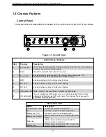
Страница 8: ...dicates network activity on LAN1 when flashing 6 NIC LED Indicates network activity on LAN2 when flashing 7 Information LED Alerts operator to several states as noted in the table below 8 UID button L...

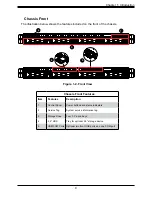
Страница 9: ...ttons and status indicators 2 Service Tag System service information tag 3 Storage Drive Four 3 5 drive bays 4 2 5 HDD Tray for optional 2 5 storage device 5 USB COM Ports Optional two front USB ports...

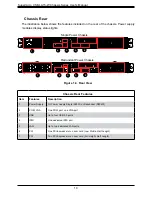
Страница 10: ...Item Features Description 1 Power Supply 1U Power Supply Single 563W or Redundant R504W 2 COM VGA One COM port one VGA port 3 USB Up to four USB 3 0 ports 4 IPMI One dedicated IPMI port 5 LAN Up to t...

Страница 11: ...be prominently displayed on the outside of the shipping carton and mailed prepaid or hand carried Shipping and handling charges will be applied for all orders that must be mailed when service is compl...

Страница 12: ...the rack Please read this section in its entirety before you begin the installation Choosing a Setup Location The chassis should be situated in a clean dust free area that is well ventilated Avoid ar...

Страница 13: ...ver from power surges and voltage spikes and to keep your system operating in case of a power failure Allow any drives and power supply modules to cool before touching them When not servicing always k...

Страница 14: ...lar attention should be given to power supply connections other than the direct connections to the branch circuit i e the use of power strips etc To prevent bodily injury when mounting or servicing th...

Страница 15: ...e rails fit a rack between 26 and 33 05 deep Identifying the Sections of the Rack Rails The chassis package includes a rail set that includes the inner and outer rail pieces that attaches to the rack...

Страница 16: ...nd Hole Bracket with Square Pegs A B 2 3 1 4 Assembling the Outer Rails Each outer rail comes in two sections that must be assembled before mounting onto the rack Assembling the Outer Rails 1 Identify...

Страница 17: ...nt of the rack C Push the rail into the rack until the quick release bracket snaps into place securing the rail to the rack Keep the rail horizontal 2 Adjust the rail to reach just past the full depth...

Страница 18: ...is to install the server into the rack Installing the Chassis into a Rack 1 Confirm that the outer rails are installed on the rack 2 Align the chassis with the front of the out rails on the rack 3 Sli...

Страница 19: ...s on either side of the chassis four total First determine how far follow the server will extend out the front of the rack Larger chassis should be positioned to balance the weight between front and b...

Страница 20: ...Please follow the procedures given in each section 3 1 Removing Power Use the following procedure to ensure that power has been removed from the system This step is necessary when removing or install...

Страница 21: ...the Top Cover 1 Remove screws 1 and 2 as shown below 2 Slide cover towards the rear as show in 3 then lift the top cover up in 4 Check that all ventilation openings on the top cover and the top of the...

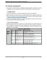
Страница 22: ...carrier has two LED indicators an activity indicator and a status indicator For RAID configurations using a controller the meaning of the status indicator is described in the table below For OS RAID...

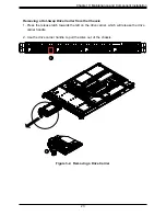
Страница 23: ...g a Hot Swap Drive Carrier from the Chassis 1 Press the release latch towards the left on the drive carrier which will release the drive carrier handle 2 Use the drive carrier handle to pull the drive...

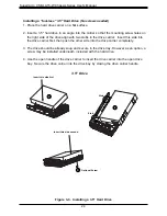
Страница 24: ...wo stubs in the drive carrier Insert this side into the drive carrier first then push the other side into the drive carrier completely 3 The drive should be already snug and secure in the drive tray H...

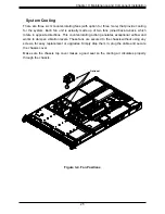
Страница 25: ...h rotate in opposite directions This counter rotating action generates exceptional airflow and works to dampen vibration levels These fans are secured to the chassis without using any screws for easy...

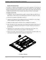
Страница 26: ...chassis cover open 2 Power down the system as described in section 3 1 3 Unplug the fan cable from the serverboard and remove the failed fan from the chassis The fan is designed to be pulled out there...

Страница 27: ...us See Control Panel in Chapter 1 for details Overheating There are several possible responses if the system overheats Overheat Temperature Setting Some backplanes allow the overheat temperature to be...

Страница 28: ...g Amber When blinking indicates that the power supply has a warning condition and continues to operate Solid Amber When illuminated indicates that the power supply is plugged in and is in an abnormal...

Страница 29: ...lies need to be replaced then a power down is required and unplug the AC cord from the module to be replaced 7 On the back of the module push the release lever to the right as illustrated in the previ...

Страница 30: ...r Card Bracket and Expansion Slots Expansion Card Configurations Slot Mechanical 1 Low profile half length 2 Full height half length 3 Full height half length Full height 4 2 Low profile 2 5 Full leng...

Страница 31: ...hile aligning the riser card bracket with the rear of the chassis 6 If necessary connect power cables to one of the 8 pin power connectors on the motherboard Installing a Low Profile Internal Expansio...

Отзывы: