


2-16
A1SAM/A1SRM Series Motherboard User’s Manual
Power Button
OH/Fan Fail/PWR Fail/
LED Cathode
1
NIC1 Link LED
Reset Button
2
Power Fail LED
HDD LED
FP PWRLED
Reset
PWR
3.3 V
3.3V Stby
UID LED Cathode
Ground
Ground
19
20
3.3V
X
Ground
NMI
X
NIC2 Link LED
3.3V Stby
3.3V Stby
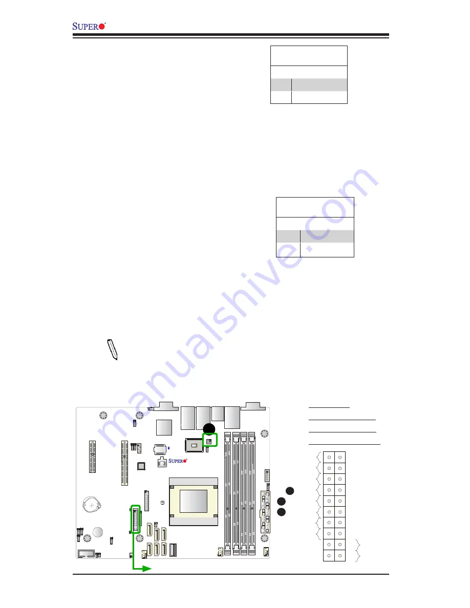
A. HDD LED
B. NIC1 (LAN1) LED
C. NIC2 (LAN2) LED
D. JPK1: LAN3/4 LED
A
B
HDD LED
The HDD LED connection is located
on pins 13 and 14 of JF1. Attach a
cable here to indicate the status of
HDD-related activities, including IDE,
SATA activities. See the table on the
right for pin definitions.
HDD LED
Pin Definitions (JF1)
Pin# Definition
13
3.3V Standby
14
HD LED
NIC1/NIC2 (LAN1/LAN2)
The NIC (Network Interface Control
-
ler) LED connection for LAN port 1
is located on pins 11 and 12 of JF1,
and the LED connection for LAN Port
2 is on Pins 9 and 10. NIC1 LED and
NIC2 LED are 2-pin NIC LED head
-
ers. Attach NIC LED cables to NIC1
and NIC2 LED indicators to display
network activities. Refer to the table
on the right for pin definitions.
Note:
LAN3/LAN4 LED Indi
-
cators are localted at JPK1.
Refer to Page 2-23 for more
information on JPK1.
LAN1/LAN2 LED
Pin Definitions (JF1)
Pin# Definition
9/11
3.3V Standby
10/12
NIC Link LED
C
JPI2C1
JL1
JOH1
JF1
JPW1
JLAN2
JLAN1
JBT1
LED8
LED7
JPK1
SP1
JBAT1
JWD1
JPB1
JI2C2
JI2C1
JPG1
JPL1
JSD1
JTP
M1
JIP
MB1
JVGA1
JUIDB1
COM2
JD1
I-SA
TA1
I-SA
TA0
I-SA
TA5
I-SA
TA4
1
I-SA
TA3
I-SA
TA2
FAN3
FAN2
FAN1
CPU1 SL
O
T4 PCI-E 2.0 X4
USB6
LAN3/4 LED
LAN2/LAN4
DIMMB2
DIMM
A2
USB0/1
BUZZER
IPMI_LAN
BATTERY
DIMMB1
CPU1 SL
O
T6 PCI-E 2.0 X8
LAN1/LAN3
DIMM
A1
USB4/5
COM1
A1SAM/A1SRM Series
Rev. 1.01
USB 2/3
FPC
TRL
LED3
BIOS
SoC Processor
BMC
PHY
JBR1
JPUSB1
JSTB
Y1
PWRI2C
LED2
D