


31
Chapter 3: Motherboard Connections
Control Panel
JF1 contains header pins for various buttons and indicators that are normally located on a
control panel at the front of the chassis. These connectors are designed specifically for use
with Supermicro chassis. See the figure below for the descriptions of the front control panel
buttons and LED indicators.
OH/Fan Fail LED
20
NIC1 Activity LED
19
HDD LED
FP PWRLED
3.3V Stby
3.3V Stby
UID LED*
X
Ground
NMI
X
NIC2 Activity LED
3.3V Stby
3.3V Stby
Power Button
Reset Button
Reset
PWR
Ground
Ground
1
2
3.3V*
Power Fail LED*
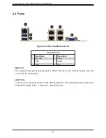
Figure 3-1. JF1: Control Panel Pins
Power Button
The Power Button connection is located on pins 1 and 2 of JF1. Momentarily contacting both
pins will power on/off the system. This button can also be configured to function as a suspend
button. To turn off the power when the system is in suspend mode, press the button for 4
seconds or longer. Refer to the table below for pin definitions.
Power Button
Pin Definitions (JF1)
Pin#
Definition
1
Power On
2
Ground
Reset Button
The Reset Button connection is located on pins 3 and 4 of JF1. Attach it to a hardware reset
switch on the computer case. Refer to the table below for pin definitions.
Reset Button
Pin Definitions (JF1)
Pin#
Definition
3
Reset
4
Ground


