


29
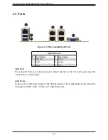
Chapter 3: Motherboard Connections
Speaker Header
On the JD1 header, pins 4-7 are for the external speaker.
Speaker Connector
Pin Definitions
Pin#
Definition
1
3.3V
2
PWR_LED_IN
3
PWR_LED_IN
4
+5V
5
NC
6
NC
7
SPK_IN
Power SMB (I
2
C) Header
The Power System Management Bus (I
2
C) connector (JPI
2
C1) monitors the power supply,
fan, and system temperatures. Refer to the table below for pin definitions.
Power SMB Header
Pin Definitions
Pin#
Definition
1
Clock
2
Data
3
PWRFAIL_N
4
Ground
5
NC
System Management Bus Header
A System Management Bus header for additional slave devices or sensors is located at JSMB.
See the table below for pin definitions.
SMBus Header
Pin Definitions
Pin#
Definition
1
Data
2
Ground
3
Clock
4
NC


