background image

Appendix C: Intel HostRAID Setup Guidelines

C-7

Creating a RAID 5 Set (Parity):

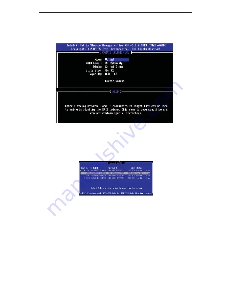
a. Select "Create RAID Volume" from the main menu and press the <Enter> key. 

The following screen will appear:

b. Specify a name for the RAID 5 set and press <Enter>. 

c. When the Raid Level is highlighted, use the <Up Arrow>, <Down Arrow> keys 

to select  RAID 5 (Parity) and hit <Enter>. 

d. When the Disk item is highlighted, press <Enter> to select the HDD to confi gure 

as RAID.  The following pop-up screen (*See the note on Page C-3) displays:

e. Use  the <Up Arrow>, <Down Arrow> keys to highlight a drive and press 

<Space> to select it. A triangle appears to confi rm the selection of the drive.

f. Use  the <Up Arrow>, <Down Arrow> keys to select the stripe size, ranging from 

4 KB to 128 KB for the RAID 5 array, and hit <Enter>. (Note: For a server, please 

use a lower stripe size, and for a multimedia system, use a higher stripe size. The 

default stripe size is 128 KB.)

g. Enter your desired RAID volume capacity and press <Enter> when the capacity 

item is highlighted. The default setting is the maximum capacity allowed.

h.  Press Enter when the Create Volume item is highlighted. A warning message 

displays.

i.  When  asked  "Are  you  sure  you  want  to  create  this  volume  (Y/N),  press  "Y"  to 

create the RAID volume, or type "N" to go back to the Create Volume menu.

Содержание 7045A-C3

Страница 1: ...SERIES3800 S120T USER S MANUAL 1 0...

Страница 2: ...THE COSTS OF REPAIRING REPLACING INTEGRATING INSTALLING OR RECOVERING SUCH HARDWARE SOFTWARE OR DATA Any disputes arising between manufacturer and customer shall be governed by the laws of Santa Clar...

Страница 3: ...es a checklist of the main components included with the server system and describes the main features of the X7DCA 3 X7DCA i serverboard and the SC743TQ 865 SQ chassis which comprise the SERIES3800 S1...

Страница 4: ...his chapter when adding or removing processors or main memory and when reconfiguring the serverboard Chapter 6 Advanced Chassis Setup Refer to Chapter 6 for detailed information on the SC743TQ 865 SQ...

Страница 5: ...v Preface Notes...

Страница 6: ...1 3 Front Control Panel 1 3 I O Backplane 1 4 Cooling System 1 4 1 4 Contacting Supermicro 1 6 Chapter 2 Server Installation 2 1 Overview 2 1 2 2 Unpacking the System 2 1 2 3 Preparing for Setup 2 1...

Страница 7: ...Ds 3 3 SAS Drives 3 3 SATA Drives 3 3 Chapter 4 System Safety 4 1 Electrical Safety Precautions 4 1 4 2 General Safety Precautions 4 2 4 3 ESD Precautions 4 3 4 4 Operating Precautions 4 4 Chapter 5 A...

Страница 8: ...nt Control Panel 6 3 6 3 System Fans 6 4 Fan Failure 6 4 Replacing Chassis Cooling Fans 6 4 6 4 Drive Bay Installation 6 6 SAS SATA Backplane 6 7 Installing Components in the 5 25 Drive Bays 6 8 6 5 P...

Страница 9: ...SERIES3800 S120T 7045A C3 7045A CT as listed below Two 2 8 cm hot swap PWM SuperQuiet chassis fans FAN 0104L4 One 1 9 cm PWM SuperQuiet exhaust fan FAN 0103L4 Two 2 CPU heat sinks SNK P0034AP4 One 1 3...

Страница 10: ...ize and speed to be installed two at a time See Chapter 5 Section 5 for details Onboard SAS An onboard LSI 1068 SAS controller is integrated into the X7DCA 3 only which supports eight SAS hard drives...

Страница 11: ...eneral outline of the main features of the SC743TQ 865 SQ server chassis System Power The 7045A C3 7045A CT features a single 865W power supply This power supply unit has been designed to operate at a...

Страница 12: ...n innovative Super Quiet cooling design that provides sufficient cooling at very low noise level ideal for a workplace envi ronment The chassis includes two 8 cm hot plug PWM Pulse Width Modulation sy...

Страница 13: ...2 Inernal SOL PCI Exp x4 PCI E x16 IDE USB 2 0 3 0 Gb S Port Ports Port 0 MCH Processor 2 ICH9 PCI Exp x16 DMI Lane 5 Lanes 1 4 FWH TPM PCI Exp x4 LPC COM1 External SIO W83627 PCI 33MHz KB MS VRD 6 7...

Страница 14: ...pe Address Super Micro Computer B V Het Sterrenbeeld 28 5215 ML s Hertogenbosch The Netherlands Tel 31 0 73 6400390 Fax 31 0 73 6416525 Email sales supermicro nl General Information support supermicro...

Страница 15: ...ad to Section 2 5 2 2 Unpacking the System You should inspect the box the system was shipped in and note if it was damaged in any way If the server itself shows damage you should file a damage claim w...

Страница 16: ...ly extended to the floor with the full weight of the rack resting on them In single rack installation stabilizers should be attached to the rack In multiple rack installations the racks should be coup...

Страница 17: ...Equipment should be mounted into a rack so that the amount of airflow required for safe operation is not compromised Mechanical Loading Equipment should be mounted into a rack so that a hazardous con...

Страница 18: ...uctions that came with the rack unit you are using Identifying the Sections of the Rack Rails The optional rackmount kit includes two rack rail assemblies Each of these as semblies consist of three se...

Страница 19: ...hassis rail sections you just removed along the side of the chassis making sure the screw holes line up Note that these two rails are left right specific Screw the rail securely to the side of the cha...

Страница 20: ...Position the fixed rack rail sliding rail guide assemblies at the desired location in the rack keeping the sliding rail guide facing the inside of the rack Screw the assembly securely to the rack usin...

Страница 21: ...se first keeping in mind that they are left right specific marked with L and R Then line up the rear of the chassis rails with the front of the rack rails Slide the chassis rails into the rack rails k...

Страница 22: ...here it says push then lift the latch to release the cover You can then lift the cover from the chassis to gain full access to the inside of the server See Figure 2 5 Checking the Components and Setup...

Страница 23: ...be accessed from the front of the server For servicing the CD 1 ROM IDE hard drives and floppy drives you will need to remove the top left chassis cover The SAS SATA disk drives can be installed and r...

Страница 24: ...the chassis The system component layout was carefully designed to promote sufficient airflow through the chassis Note that all power and data cables have been routed in such a way that they 2 do not b...

Страница 25: ...status of the system and the activity and health of specific components 3 2 Control Panel Buttons There are two push buttons located on the front of the chassis a power on off button and a reset butt...

Страница 26: ...to take 1 2 Power Indicates power is being supplied to the system s power supply This LED should normally be on when the system is operating HDD Indicates IDE channel activity On the 7045A C3 7045A C...

Страница 27: ...When illuminated the green LED on the front of the SAS drive carrier indicates drive activity A connection to the SAS backplane enables this LED to blink on and off when that particular drive is being...

Страница 28: ...3 4 SERIES3800 S120T 7045A C3 7045A CT User s Manual Notes...

Страница 29: ...hen disconnecting power you should first power down the system with the operating system and then unplug the power cords of all the power supply units in the system When working around exposed electri...

Страница 30: ...rcuits or be pulled into a cooling fan Remove any jewelry or metal objects from your body which are excellent metal conductors that can create short circuits and harm you if they come into contact wit...

Страница 31: ...use Touch a grounded metal object before removing the board from the antistatic bag Do not let components or PCBs come into contact with your clothing which may retain a charge even if you are wearing...

Страница 32: ...t the chassis cover is in place when the 7045A C3 7045A CT is operating to assure proper cooling Out of warranty damage to the 7045A C3 7045A CT system can occur if this practice is not strictly follo...

Страница 33: ...ant to handle them very carefully see previous chapter To prevent the serverboard from bending keep one hand under the center of the board to support it when handling The following measures are genera...

Страница 34: ...i requires a chassis big enough to support a 12 x 13 2 serverboard such as Supermicro s SC743TQ 865 SQ Make sure that the I O ports on the serverboard align properly with their 3 respective holes in...

Страница 35: ...O 1 T SGPIO 2 Important Make sure the the cables do not come into contact with the fans Connecting Power Cables The X7DCA 3 X7DCA i has a 24 pin primary power supply connector JPW3 for connection to t...

Страница 36: ...c Vcc Vcc Vcc Reset Button Power Button Ground x Key Power On LED HDD LED NIC1 LED NIC2 LED OH Fan Fail LED Power Fail LED Ground Ground 2 1 20 19 12 16 15 13 14 2 5 3 6 9 1 11 7 4 17 I O Port Definit...

Страница 37: ...rd last and remove it before adding remov ing or changing any components Make sure to install the processor into the CPU socket before you install the CPU heat sink Intel s boxed Xeon CPU package cont...

Страница 38: ...opposite sides Align pin1 of the CPU the corner 4 marked with a triangle with the notched corner of the CPU socket Find the corner of the CPU that 5 has a semi circle cutout below a gold dot CPU key T...

Страница 39: ...thumb to gently push the 8 load lever down until it snaps into the retention clasp If the CPU is properly installed 9 into the socket the PnP cap will be automatically released from the load plate wh...

Страница 40: ...removing the CPU or the heat sink However if you do need to uninstall the heat sink please follow these instructions to avoid damaging the CPU or the CPU socket Installation and Removal of the Heat Si...

Страница 41: ...to place in the slot 3 Repeat for all modules see step 1 above Memory Support The X7DCA 3 X7DCA i supports up to 32 GB of registered ECC DDR2 667 533 in 6 slots Populating slots with a pair or pairs o...

Страница 42: ...t on the slot Notch Notch Release Tab Release Tab Possible System Memory Allocation Availability System Device Size Physical Memory Remaining Available 4 GB Total System Memory Firmware Hub flash memo...

Страница 43: ...ard Before installing a PCI add on card make sure you install it into a slot that supports the speed of the card see step 1 above Begin by removing the PCI slot shield for the slot you wish to populat...

Страница 44: ...120T 7045A C3 7045A CT User s Manual Figure 5 4 X7DCA 3 X7DCA i Layout not drawn to scale 5 8 Serverboard Details X7DCA 3 Note the X7DCA i shares the same layout as the X7DCA 3 but has no SAS com pone...

Страница 45: ...IDE IDE Drive Connector I SATA0 I SATA5 SATA Ports J5 Power System Management I2 C Header J6 Power Supply SMBus I2 C Header JD1 Onboard Speaker Power LED JF1 Control Panel Connector JL1 Chassis Intru...

Страница 46: ...tton Pin Definitions JF1 Pin Definition 1 PW_ON 2 Ground Secondary Power Connectors JPW1 must also be connected to the power supply See the table on the right for pin definitions Main ATX Power Supply...

Страница 47: ...IC2 LED Pin Definitions JF1 Pin Definition 9 Vcc 10 Ground NIC2 LAN2 LED The LED connections for LAN2 are on pins 9 and 10 of JF1 Attach an LED cable to display network activ ity See the table on the...

Страница 48: ...le on the right for pin definitions NMI Button Pin Definitions JF1 Pin Definition 19 Control 20 Ground Fan Header Pin Definitions FAN1 8 Pin Definition 1 Ground Black 2 12V Red 3 Tachometer 4 PWM Cont...

Страница 49: ...round 3 Wake up LAN1 2 Ethernet Ports Two Ethernet ports designated LAN1 and LAN2 are located beside the VGA port on the I O backplane These ports accept RJ45 type cables Wake On Ring The Wake On Ring...

Страница 50: ...aker If you wish to use the onboard speaker please close pins 6 7 See the table on the right for speaker pin definitions Power LED Speaker Connector JD1 Pin Setting Definition Pins 6 7 Internal Speake...

Страница 51: ...on the right for pin definitions PS 2 Keyboard and Mouse Port Pin Definitions Pin Definition 1 Data 2 NC 3 Ground 4 VCC 5 Clock 6 NC Power SMB I2 C Connector The power SMB I2 C connector is used to mo...

Страница 52: ...ble from your CD drive to the CD header that fits your cable s connector Only one CD header can be used at any time Front Panel Audio Control When front panel headphones are plugged in the back panel...

Страница 53: ...er Closed means the jumper is on both pins and Open means the jumper is either on only one pin or completely removed CMOS Clear JBT1 is used to clear CMOS which will also clear any passwords Instead o...

Страница 54: ...eir own application software in order to disable the Watch Dog Timer Watch Dog Jumper Settings JWD Jumper Setting Definition Pins 1 2 Reset Pins 2 3 NMI Open Disabled I2 C to PCI X Slots Jumper Settin...

Страница 55: ...peed LED LAN1 2 LED Connection Speed Indicator LED Color Definition Off 10 MHz Green 100 MHz Amber 1 GHz Onboard Power LED LE1 An Onboard Power LED is located at LE1 This LED Indicator is lit when the...

Страница 56: ...the onboard IDE connector interface and the other connector s to your hard drive s Consult the documentation that came with your disk drive for details on actual jumper locations and settings for the...

Страница 57: ...ta 7 4 Host Data 8 5 Host Data 6 6 Host Data 9 7 Host Data 5 8 Host Data 10 9 Host Data 4 10 Host Data 11 11 Host Data 3 12 Host Data 12 13 Host Data 2 14 Host Data 13 15 Host Data 1 16 Host Data 14 1...

Страница 58: ...Definition Pin Definition 1 Ground 2 FDHDIN 3 Ground 4 Reserved 5 Key 6 FDEDIN 7 Ground 8 Index 9 Ground 10 Motor Enable 11 Ground 12 Drive Select B 13 Ground 14 Drive Select B 15 Ground 16 Motor Ena...

Страница 59: ...ortant to handle them very carefully The following measures are generally sufficient to protect your equipment from static discharge Precautions Use a grounded wrist strap designed to prevent static d...

Страница 60: ...6 2 SERIES3800 S120T 7045A C3 7045A CT User s Manual 8 SAS SATA Drive Bays behind locking bezel Figure 6 1 Chassis Front View System Reset Main Power Floppy Drive 5 25 Drive Bays 2 USB Ports...

Страница 61: ...n the control panel inform you of system status see Figure 6 2 for details See Chapter 5 for details on JF1 Figure 6 2 Front Control Panel LEDs Power NIC1 HDD Overheat Fan Fail Indicates power is bein...

Страница 62: ...nience Fan Failure Under normal operation the chassis fans the exhaust fan and the power supply fans run continuously The chassis fans are hot swappable and can be replaced without powering down the s...

Страница 63: ...Chapter 6 Advanced Chassis Setup 6 5 Figure 6 3 Removing a Chassis Fan...

Страница 64: ...the printed circuit board side facing down 1 so that the mounting holes align with those in the carrier Secure the drive to the carrier with four screws see Figure 6 5 2 6 4 Drive Bay Installation A...

Страница 65: ...cts and make sure no ribbon cables touch the backplane or obstruct the airflow holes Figure 6 4 Removing a SAS SATA Drive Carrier SAS SATA Backplane The SAS SATA drives plug into a SAS SATA backplane...

Страница 66: ...e holes provided Slide the DVD CD ROM into the bay and secure it to the chassis with the 2 drive carrier screws you first removed Attach the power and data cables to the drive 3 Replace the top left c...

Страница 67: ...rmicro see Contact Information in the Preface As there is only one power supply unit the server must be powered down before removing and or replacing the power supply for whatever reason Replacing the...

Страница 68: ...6 10 SERIES3800 S120T 7045A C3 7045A CT User s Manual Notes...

Страница 69: ...p battery pro vides power to the CMOS Logic enabling it to retain system parameters Each time the computer is powered on the computer is configured with the values stored in the CMOS Logic by the syst...

Страница 70: ...ys By pressing Delete immediately after turning the system on or 1 When the message shown below appears briefly at the bottom of the screen 2 during the POST Power On Self Test press the Delete key to...

Страница 71: ...e Using the arrow keys highlight the month day and year fields and enter the correct data Press the Enter key to save the data BIOS Date This field displays the date when this version of BIOS was buil...

Страница 72: ...b menu screen for detailed options of these items Set the correct configurations accordingly The items included in the sub menu are Type This option allows the user to select the type of IDE hard driv...

Страница 73: ...city in the LBA Format Multi Sector Transfers This item allows the user to specify the number of sectors per block to be used in multi sector transfer The options are Disabled 4 Sectors 8 Sectors and...

Страница 74: ...le will be available The options are Enabled and Disabled ICH RAID Code Base Available when SATA RAID is Enabled Select Intel to enable Intel s SATA RAID firmware Select LSI to use LSI s HostRAID firm...

Страница 75: ...to the following settings QuickBoot Mode If enabled this feature will speed up the POST Power On Self Test routine by skipping certain tests after the computer is turned on The settings are Enabled an...

Страница 76: ...and Last State Watch Dog If enabled this option will automatically reset the system if the system is not active for more than 5 minutes The options are Enabled and Disabled Summary Screen This setting...

Страница 77: ...ble this function Select Write Through to allow data to be cached into the buffer and written into the system memory at the same time Select Write Protect to prevent data from being written into the b...

Страница 78: ...xp x16 Access the submenu for each of the settings above to make changes to the fol lowing Option ROM Scan When enabled this setting will initialize the device expansion ROM The options are Enabled an...

Страница 79: ...Disabled SERR Signal Condition This setting specifies the ECC Error conditions that an SERR is to be asserted The options are None Single Bit Multiple Bit and Both 4GB PCI Hole Granularity This featu...

Страница 80: ...er to Intel s web site for more information The options are Disabled and Enabled Machine Checking Available when supported by the CPU Set to Enabled to activate the function of Machine Checking and al...

Страница 81: ...e the hardware components that are used in conjunction with software programs to prefetch data in order to shorten execution cycles and maximize data processing efficiency The options are Disabled and...

Страница 82: ...the submenu to make changes to the following settings KBC Clock Input This setting allows you to select clock frequency for KBC The options are 6MHz 8MHz 12MHz and 16MHz Serial Port A This setting all...

Страница 83: ...This setting allows you to select the IRQ interrupt request for the parallel port The options are IRQ5 and IRQ7 Mode This feature allows you to specify the parallel port mode The options are Output o...

Страница 84: ...s as read Clear All DMI Event Logs Select Yes and press Enter to clear all DMI event logs The options are Yes and No XConsole Redirection Access the submenu to make changes to the following settings C...

Страница 85: ...ace items CPU1 Temperature CPU1 Second Core CPU2 Temperature CPU2 Second Core PECI Agent 1 PECI Agent 2 PECI Agent 3 PECI Agent 4 Temperature System Temperature Fan1 Fan8 Speeds If the feature of Auto...

Страница 86: ...tings For the Windows OS to adopt the BIOS temperature threshold settings please change the SDIII settings to be the same as those set in the BIOS XIPMI Available only when an IPMI card is installed i...

Страница 87: ...This feature allows the user to set the time value in minutes for the previous item OS Boot Watch Dog by keying in a desired number in the blank The default setting is 10 minutes Please ignore this op...

Страница 88: ...7 20 SERIES3800 S120T 7045A C3 7045A CT User s Manual XRealtime Sensor Data This feature display information from motherboard sensors such as temperatures fan speeds and voltages of various components...

Страница 89: ...ord has been entered for the system Clear means such a password has not been used and Set means a supervisor password has been entered for the system User Password Is This indicates if a user password...

Страница 90: ...en prompted type the user s password in the dialogue box to set or to change the user s password which allows access to the system at boot up Password on Boot This setting allows you to determine if a...

Страница 91: ...he devices included in the candidate list above are currently disabled Use the key or key to move the device up or down Use the f key or the r key to specify the type of a USB device either fixed or r...

Страница 92: ...tup utility Exit Discarding Changes Highlight this item and hit Enter to exit the BIOS Setup utility without saving any changes you may have made Load Setup Defaults Highlight this item and hit Enter...

Страница 93: ...ed Keyboard controller failed test May require replacing keyboard controller Keyboard locked Unlock key switch Unlock the system to proceed Monitor type does not match CMOS Run SETUP Monitor type not...

Страница 94: ...tup If the failure was caused by incorrect values and they are not corrected the next boot will likely fail On systems with control of wait states improper Setup settings can also terminate POST and c...

Страница 95: ...error Fail Safe Timer takes too long device Address Conflict Address conflict for specified device Allocation Error for device Run ISA or EISA Configuration Utility to resolve resource conflict for th...

Страница 96: ...e to display all installed I2O block stor age devices Operating system not found Operating system cannot be located on either drive A or drive C Enter Setup and see if fixed disk and drive A are prope...

Страница 97: ...the I2O Configuration Utility One or more unclaimed block storage devices have the Configuration Request bit set in the LCT Run an I2O Configuration Utility e g the SAC utility System BIOS shadowed Sy...

Страница 98: ...A 6 SERIES3800 S120T 7045A C3 7045A CT User s Manual Notes...

Страница 99: ...video and write the error in the top left corner of the screen The following is a list of codes that may be written to port 80h POST Code Description 01h IPMI Initialization 02h Verify Real Mode 03h D...

Страница 100: ...ut down 38h Shadow system BIOS ROM 3Ah Auto size cache 3Ch Advanced configuration of chipset registers 3Dh Load alternate registers with CMOS values 41h Initialize extended memory for RomPilot optiona...

Страница 101: ...nd IRQs optional 81h Late POST device initialization 82h Detect and install external RS232 ports 83h Configure non MCD IDE controllers 84h Detect and install external parallel ports 85h Initialize PC...

Страница 102: ...rminate QuietBoot optional B6h Check password optional B7h Initialize ACPI BIOS and PPM Structures B9h Prepare Boot BAh Initialize SMBIOS BCh Clear parity checkers BDh Display MultiBoot menu BEh Clear...

Страница 103: ...rupt vectors F1h Initialize Run Time Clock F2h Initialize video F3h Initialize System Management Manager F4h Output one beep F5h Clear Huge Segment F6h Boot to Mini DOS F7h Boot to Full DOS If the BIO...

Страница 104: ...B 6 SERIES3800 S120T 7045A C3 7045A CT User s Manual Notes...

Страница 105: ...version of the ICH9R SATA RAID Utility can only support Windows XP 2000 2003 Operating Systems Serial ATA SATA Serial ATA SATA is a physical storage interface that uses a single cable with a minimum...

Страница 106: ...he HDD partition size without any data Configuring BIOS settings for SATA RAID Functions Native Mode 1 Press the Del key during system bootup to enter the BIOS Setup Utility Note If it is the first ti...

Страница 107: ...appears after Power On Self Test b When you see the above screen press the Ctrl and the I keys simultane ously to have the main menu of the SATA RAID Utility appear Note All graphics and screen shots...

Страница 108: ...t a drive and press Space to select it A triangle appears to confirm the selection of the drive f Use the Up Arrow Down Arrow keys to select the stripe size ranging from 4 KB to 128 KB for the RAID 0...

Страница 109: ...select the previous menu c When RAID Level item is highlighted press the Up Arrow Down Arrow keys to select RAID 1 Mirror and hit Enter d When the Capacity item is highlighted enter your RAID volume...

Страница 110: ...Arrow Down Arrow keys to select the stripe size from 4 KB to 128 KB for your RAID 10 and hit Enter The default setting is 6 4KB Note For a server please use a lower stripe size and for a multimedia s...

Страница 111: ...ight a drive and press Space to select it A triangle appears to confirm the selection of the drive f Use the Up Arrow Down Arrow keys to select the stripe size ranging from 4 KB to 128 KB for the RAID...

Страница 112: ...disk drives when deleting a RAID set a From the main menu select item2 Delete RAID Volume and press Enter b Use the Up Arrow Down Arrow keys to select the RAID set you want to delete and press Del A...

Страница 113: ...he RAID set drive A Warning message displays d Press Y to reset the drive or type N to go back to the main menu Exiting the Intel Matrix Storage Manager Utility a From the main menu select item4 Exit...

Страница 114: ...troller from the list indicated in the XP 2000 2003 Setup Screen and press the Enter key f Press the Enter key to continue the installation process If you need to specify any additional devices to be...

Страница 115: ...M Memory Capacity Six 240 pin DIMM slots that can support up to 32 GB of ECC DDR2 667 533 SDRAM Note 2 way interleaved memory requires memory to be installed two modules at a time See the memory secti...

Страница 116: ...648 mm Weight Gross Bare Bone 64 lbs 29 1 kg System Cooling Two 2 8 cm low noise chassis fans One 1 9 cm low noise exhaust fan Two 2 active CPU heat sinks System Input Requirements AC Input Voltage 1...

Страница 117: ...N 61000 4 5 EN 61000 4 6 EN 61000 4 8 EN 61000 4 11 Safety EN 60950 IEC 60950 Compliant UL Listed USA CUL Listed Canada TUV Certified Germany CE Marking Europe California Best Management Practices Reg...

Страница 118: ...D 4 SERIES3800 S120T 7045A C3 7045A CT User s Manual Notes...

Отзывы: