Chapter 5: Advanced Serverboard Setup
5-3
5-2
S
UPER
S
TORAGE
S
YSTEM 6047R-E1R36N User's Manual
5-2 Connecting Cables
Several cables need to be connected to the serverboard. These include the data
cables for the peripherals and control panel and the power cables.
Connecting Data Cables
The cables used to transfer data from the peripheral devices have been carefully
routed to prevent them from blocking the flow of cooling air that moves through
the system from front to back. If you need to disconnect any of these cables, you
should take care to keep them routed as they were originally after reconnecting
them (make sure the red wires connect to the pin 1 locations). The following data
cables (with their locations noted) should be connected. (See the layout on page
5-13 for connector locations.)
•
Control Panel cable (JF1)
•
USB cable for front side access (USB4/5)
Important!
Make sure the the cables do not come into contact with the fans.
Connecting Power Cables
The X9DRi-LN4F+ has a 24-pin primary power supply connector (JPW1) for con-
nection to the ATX power supply. In addition, there are two 8-pin 12V processor
power connectors (JPW2 and JPW3) that must be connected to your power supply.
See Section 5-9 for power connector pin definitions.
Connecting the Control Panel
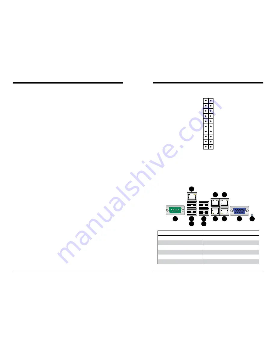
JF1 contains header pins for various front control panel connectors. See Figure 5-1
for the pin locations of the various front control panel buttons and LED indicators.
All JF1 wires have been bundled into a single cable to simplify this connection. Make
sure the red wire plugs into pin 1 as marked on the board. The other end connects
to the Control Panel PCB board, located just behind the system status LEDs on
the chassis. See Chapter 5 for details and pin descriptions.
5-3 Rear I/O Ports
The I/O ports are located on the backplane of the motherboard. See Figure 5-2
below for the descriptions of the various I/O ports.
Figure 5-1. Control Panel Header Pins
Figure 5-2. Rear I/O Ports
NMI
x (Key)
3.3V
ID/UID/SW/3.3V Stby
NIC1 Activity LED
NIC2 Activity LED
Red + (Blue Cathode
3.3V
Reset (Button)
Power (Button)
Ground
x (Key)
Power On LED
HDD LED
NIC1 Link LED
NIC2 Link LED
OH/Fan Fail LED
Power Fail LED
Ground
Ground
2 1
20 19
Rear I/O Ports
1
COM Port 1
7
LAN Port 1
2
USB Port 0
8
LAN Port 3
3
USB Port 1
9
LAN Port 2
4
Dedicated IPMI LAN
10
LAN Port 4
5
USB Port 2
11
VGA Port
6
USB Port 3
12
UID Switch
1
9
1
8
7
5
6
3
4
2
1
10
1
11
1
12
Содержание 6047R-E1R36N
Страница 1: ... SUPER STORAGE SYSTEM 6047R E1R36N SUPER USER S MANUAL 1 1 ...
Страница 17: ...3 4 SUPERSTORAGESYSTEM 6047R E1R36N User s Manual Notes ...
Страница 28: ...4 20 SUPERSTORAGESYSTEM 6047R E1R36N User s Manual Notes ...
Страница 70: ...7 32 SUPERSTORAGESYSTEM 6047R E1R36N User s Manual Notes ...
Страница 72: ...A 2 SUPERSTORAGESYSTEM 6047R E1R36N User s Manual Notes ...