background image


7

MOTORIZED TREADMILL PRE-ASSEMBLY 

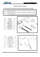
Handrail control button and heart rate strap are optional items in the package 


1.Heart rate can be measured in this treadmill. Attach strap to chest during exercise, the heart rate value will 
display on the PULSE window. 
2. Except using the control button on the console, the control button on the handrail can also be used to 
adjust speed and elevation. The control button on the left handrail is for elevation while the right handrail 
button is for speed adjustment. 
3. Under START/READY condition, if you did not hold grip pulse sensor, then PULSE window will display HP, 
when you hole the both sides of grip pulse sensor, you will see the PULSE window display the heart rate values.


ITEM Description  Qty 

Computer set 

Frame 

Left Upright 

D Right 

Upright 1 

Left Side Cover 

Right Side Cover 

G Left 

handrail 1 

H Right 

handrail 1 

Left handrail cover 

Right handrail cover 

Bottle holder 

L Bottle 1 

ITEM Description  Qty 

a Bolt 

M8xP1.25x15 10 

b Bolt 

M5xP0.8x10 4 

c Bolt 

M8xP1.25x60 4 

d Bolt 

ψ

5x25 2 

Allen Wrench   5mm 

Allen Wrench   6mm 

g SILICON 1 
h Safety 

Key/Clip 1 

i Power 

Cord 1 

Содержание Cardio-zone

Страница 1: ...SuperSport Club Fold Away Super Gym s FitnessBlowout com 2210 S Sepulveda Blvd Los Angeles CA 90064 Phone 800 FIT 4 LESS or 800 348 4537 Fax 310 235 2008 OWNER S MANUAL ...

Страница 2: ...ual carefully before using your CardioZone SuperSport Club This will allow you to get a full understanding of all the features that CardioZone treadmills provide If you have any questions or concerns please contact Super Gym s FitnessBlowout com For service please visit http www fitnessblowout com service Register your warranty at http www fitnessblowout com warranty Super Gym s FitnessBlowout com...

Страница 3: ...2 ...

Страница 4: ...EW DRAWING 4 2 IMPORTANT SAFETY INSTRUCTIONS 5 3 GROUNDING INSTRUCTIONS 6 4 MOTORIZED TREADMILL PRE ASSEMBLY 7 5 ASSEMBLY STEPS 8 6 CAUTIONS 11 7 MAINTENANCE 12 8 COMPUTER INSTRUCTION 13 9 EXPLODED VIEW 19 10 TROUBLESHOOTING 21 11 WARRANTY 23 ...

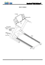
Страница 5: ...4 OVERVIEW DRAWING ...

Страница 6: ...rd or plug if it is not working properly if it has been dropped or damaged or dropped into water Return the appliance to a service center for examination and repair 5 Do not carry this appliance by supply cord or use cord as a handle 6 Keep the cord away from heated surfaces 7 Never operate the appliance with the air openings blocked Keep the air openings free of lint hair and the like 8 Never dro...

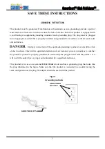
Страница 7: ...connection of the equipment grounding conductor can result in a risk of electric shock Check with a qualified electrician or serviceman if you are in doubt as to whether the product is product is properly grounded Do not modify the plug provided with the product if it will not fit the outlet have a proper outlet installed by a qualified electrician This product is for use on a nominal 110 120volt ...

Страница 8: ...utton is for speed adjustment 3 Under START READY condition if you did not hold grip pulse sensor then PULSE window will display HP when you hole the both sides of grip pulse sensor you will see the PULSE window display the heart rate values ITEM Description Qty A Computer set 1 B Frame 1 C Left Upright 1 D Right Upright 1 E Left Side Cover 1 F Right Side Cover 1 G Left handrail 1 H Right handrail...

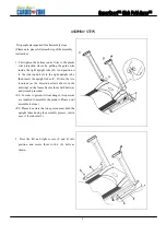
Страница 9: ...ght upright tube then insert the upright tubes C D into the two locations as the direction arrows shown in the drawing on the frame Secure them with bolts a and wrench provided P S In order to prevent it from danger two persons are required to assemble the product Please don t assemble it alone P S Please be aware that one person must hold the upright tubes during the assembly process just in case...

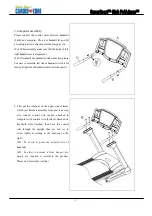
Страница 10: ...for incline Right side of handrail switch is for the speed 4 First put the computer on the upper side of frame which just finished assembly from previous step also connect control wire upper attached in computer with control wire bottom attached on treadmill after finished then have the control wire through the upright then use bolt c to screw tightly according to the drawing on the right Ps1 To a...

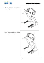
Страница 11: ...10 5 Then press left screw cover and right screw cover I and J into place and secure them with 2 d screws 6 Finally secure water holder K on computer console then the assembly is completed ...

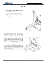
Страница 12: ...ow s direction then lift up the treadmill until POP Pin click the hole then can take the had off opposite if want to use treadmill just pull out the POP Pin as the arrow s direction then put the treadmill slowly on the floor until POP Pin click to the position Ps 1 Prevent from causing dangerous is careful if the kids are around If want to move the treadmill must fold the treadmill let hands hold ...

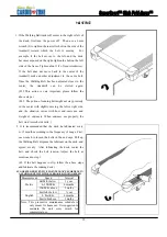
Страница 13: ...r right side and the situation varies with how end users use and weight of end users When end user use properly the belt won t scotch side rails 2 It is recommended that the deck be lubricated every 6 12 months according to the frequency of usage First use wrench to loosen the bolts in the end caps Pull up the Walking Belt dispense the lubricant on the deck and spread evenly After lubricating the ...

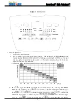
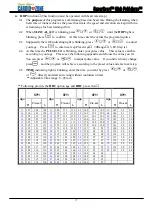
Страница 14: ... different heart rate due to age and amount of exercise 170 OVER 150 166 MIDDLE 120 146 162 LOW 117 143 157 114 137 153 111 135 149 108 131 145 105 128 140 102 124 136 99 120 132 96 116 HEART BEATS MIN 93 20 25 30 35 40 45 50 55 60 65 Age 3 Press to begin MANUAL will blink the treadmill starts with a velocity of 0 5MPH While the belt is running press to accelerate or decelerate the speed of the be...

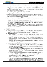
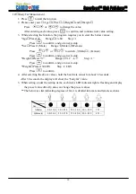
Страница 15: ... MODE function key 1 At the ready start condition press function key MANUAL LED will be blinking press or to change to MANUAL P1 P5 or HRP LED 2 MANUAL Function 2 1 While MANUAL light is blinking press MANUAL will stop blink it will continue bright TIME light will be blinking now you can adjust time 2 2 Press the motor will operate directly according to installed value 0 5MPH at the time press or ...

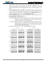
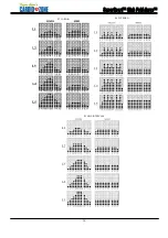
Страница 16: ...rn to the original PROGRAM setting 3 6 In each PROGRAM before L1 L5 begin they all have 1 minute for warm up It will start with each LEVEL initial velocity 3 7 P1 and P2 both has its definition as below P1 5K RUN The pre set distance in this program is 5000m 3 1mil It will be finished after you run 5000m 3 1mil and the treadmill will stop Under this mode jog is the main part purpose P2 9 HOLE The ...

Страница 17: ...16 P3 CARDIO P4 FAT BURN P5 HILL INTERVALS ...

Страница 18: ...ctly and start exercising without countdown timer Adjustable Time range 5 99 min Following provide the HRC option age and HRC pre set list BPM BPM BPM BPM Age H Pre set L Age H Pre set L Age H Pre set L Age H Pre set L 13 197 124 124 31 180 113 113 49 162 103 103 67 145 92 92 14 196 124 124 32 179 113 113 50 162 102 102 68 144 91 91 15 195 123 123 33 178 112 112 51 161 101 101 69 143 91 91 16 194 ...

Страница 19: ...nd go to next setup Height Preset 5 7 Range 3 11 6 7 Step 1 Press to confirm and go to next setup Weight Preset 150LBS Step 2 LBS Press to confirm 4 After selecting the above values hold the heart rate sensor for about 30 seconds After 30 seconds the display will show the body fat value 5 When setting under the setting items each items LED indicator light is flashing and display the pre set value ...

Страница 20: ...19 EXPLODED VIEW ...

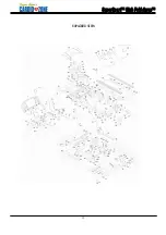
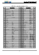
Страница 21: ...l P 1053C 2 20 Bolt M8xP1 25x15 8 82 Rear Roller Set 1 21 Bolt M10xP1 5x12 Blue Locktite 8 83 Bolt M8xP1 25x35 6 22 Double D Washer NO 2737 8 84 Sponge 20x100x1 5t 6 23 Bolt M10xP1 5x35 Blue Locktite 4 85 Running Deck 1 24 Bot M8xP1 25x40 1 86 Power Cord 1 25 Bolt ψ5x25 2 87 Control Wire Bottom 1 26 Plate L NO 2392 L 1 88 Wire Button UC 0 2 27 Plate R NO 2392 R 1 89 Side Cover Plastic P 1319 2 28 ...

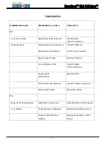
Страница 22: ... position Speed Sensor Faulty Replace S Sensor Loose Display Cable Check Display Cable connection Faulty MCB D2 LED on Replace MCB Drive Motor disconnected Check D Motor connection Drive Motor Faulty Replace D Motor E4 Body Fat Data Incomplete Heart Rate not detected Hold Heart Rate Grip Properly Loss of Data Faulty Receiver in Display Replace Heart Rate Receiver Faulty Control Board in Display Re...

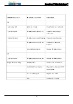
Страница 23: ...tor screw binding Clean screw and lubricate Elevation Motor out of Range Check Zero Position of E Motor E Motor Potentiometer Replace Elevation Motor E7 Elevation Motor Elevation Motor out of Range Replace Elevation Motor Display Doesn t Lit Up On Off switch Check if unit is turned on Insufficient Power Source Plug unit in a dedicated 120V 20Amp Outlet Line Cord Damaged Replace Line Cord Fuse Chec...

Страница 24: ...s in the possession of the original owner ELECTRONICS PARTS 2 Years Super Gym s FitnessBlowout com warrants the Electronic components and all original parts other than the Motor against defects in workmanship and materials for a period of two years from the date of original purchase so long as the device remains in the possession of the original owner LABOR 1 Year Super Gym s FitnessBlowout com sh...

Страница 25: ...he sole remedy of the warranty The warranty does not cover normal wear Super Gym s FitnessBlowout com expressly disclaims all other warranties express or implied including but not limited to all warranties of fitness for a particular purpose or of merchantability This warranty gives you specific legal rights and your rights may vary from state to state WARRANTY REGISTRATION Register your warranty ...

Отзывы: