background image


14

DE

EN

4  Electrical connection


Danger of death through electric 

Touching live parts can result in death.

Make sure the polarity is correct when connecting 
the modules. Reverse polarity can lead to destruction 
of the protective diodes.

Before installing junction box check the cables and 
connectors for obvious damage.

For safety reasons the junction box must not be 
opened.

Do not use the plug connectors if the plug contacts 
are dirty!

Do not install damaged solar modules!

The solar modules, and in particular the connectors 
and tools, must be dry during installation.

In exposed locations, installation of lightning protec-
tion is recommended. If lightning protection equip-
ment is already present, the solar modules must be 
integrated properly. Follow the respective current 
regulations.

During normal conditions PV module may supply a 
higher current and/or voltage than specified under 
test conditions.

For determining the voltage design values of the 
components, the current design values of the con-
ductors, the ratings of the fuses and the control units 
connected to the solar module output, the values of 
I

SC

 and U

OC

 specified on the module should be multi-

plied with a factor of 1.25.

The solar module is equipped with high-quality solar 
cables and the Tyco plug connector system, which 
is protected against reverse polarity and accidental 
contact. The connection polarity is marked. 

The maximum cable cross-section should be 4 mm

2

.

4.1  Connector system

CAUTION

The plug connectors must not be disconnected or 
connected under load current! They may be con-
nected and disconnected while voltage is present. 

4.2  Application class

Sunways Solar Modules conform to application class 
A according to the international safety standard 
EN 61730 and therefore meet the requirements of 
protection class II. 

Sunways Solar Modules can be used in systems with a 
DC voltage in excess of 120 V

DC

.

4.3  Earthing of the modules

An overview of the solar module can be found in sec-
tion 2, Your Solar Modules. A diagram indicates the 
holes for connecting the earthing cables.

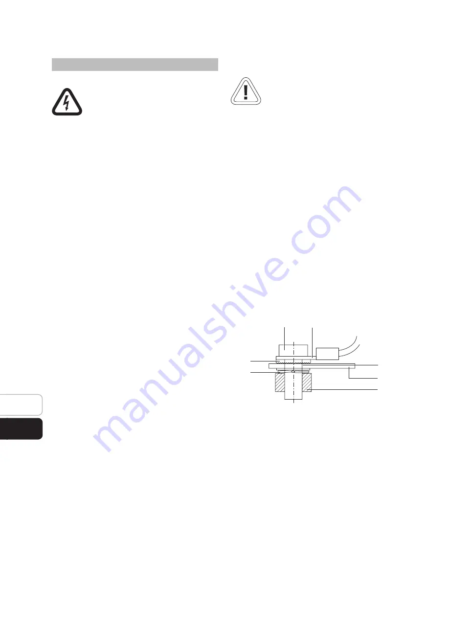
Detail view of the earthing cable connection

1  Fastening screw M4
2  Ring terminal with earthing cable
3  Hole for earthing
4  Lock washer
5  Module frame
6  Spring washer
7  Nut

Proceed as follows to ensure correct earthing of the 
modules:

1. 

Place the lock washer (4) and the ring terminal 
with the earthing cable (2) over the earthing hole 
(3) on the front of the module. 

2. 

Insert the fastening screw M4 (1). 

3

4

5

2

6

7

1

Содержание SM 240U

Страница 1: ...1 Installations und Bedienungsanweisung Sunways Solar Modules SM 245M SM 240U Deutsch English EN SETUP DE...

Страница 2: ...5...

Страница 3: ...3 Erdung der Module 7 5 Wartung und Pflege 7 6 Kenngr en der Module 7 7 Konformit tserkl rung 7 11 1 Safety first 12 2 Your Solar Modules 12 3 Installation 12 3 1 Orientation 12 3 2 Maximum series par...

Страница 4: ......

Страница 5: ...1 Installations und Bedienungsanweisung Sunways Solar Modules SM 245M SM 240U Deutsch English EN SETUP DE 3...

Страница 6: ...Module zu rechnen Daher m ssen die Module bei s mtlichen Installati ons und Verschaltungsarbeiten abgedeckt oder vom Verbraucher elektrisch getrennt werden Ansonsten besteht bei Gleichstrom f hrenden...

Страница 7: ...rd ein Abstand von 20mm empfohlen Die Module m ssen so installiert werden dass ins besondere am Kabel kein Wasser in Richtung der Kabelverschraubung an der Anschlussdose flie en kann Die Verbindungska...

Страница 8: ...hutzes zu empfehlen Bei vorhandener Blitzschutz einrichtung sind die Solarmodule mit einzubinden Beachten Sie dabei die entsprechenden g ltigen Vorschriften Auch unter blichen Bedingungen kann ein PV...

Страница 9: ...erschmutzung empfiehlt sich eine Rei nigung der vorderseitigen Glasfl che Verwenden Sie hierzu viel lauwarmes Wasser und eine weiche B rste Hierdurch k nnen Ertragseinbu en verhin dert werden VORSICHT...

Страница 10: ...5...

Страница 11: ...3 Erdung der Module 7 5 Wartung und Pflege 7 6 Kenngr en der Module 7 7 Konformit tserkl rung 7 11 1 Safety first 12 2 Your Solar Modules 12 3 Installation 12 3 1 Orientation 12 3 2 Maximum series pa...

Страница 12: ...1...

Страница 13: ...1 Installation and Operating Instructions Sunways Solar Modules SM 245M SM 240U English EN SETUP DE 11...

Страница 14: ...g all installation and wiring work the modules must therefore be covered or disconnected from the consumer load Otherwise there is a risk of arc formation on lines carrying direct current Suitable fal...

Страница 15: ...cable gland at the junction box is prevented The connection cables between the modules and towards the inverter must be installed such that the closed connectors are not permanently in water This mean...

Страница 16: ...the module should be multi plied with a factor of 1 25 The solar module is equipped with high quality solar cables and the Tyco plug connector system which is protected against reverse polarity and ac...

Страница 17: ...amage corrosion and make sure they are secure 6 Module parameters The electrical parameters can be found in the cor responding module datasheet 7 Declaration of conformity EU declaration of conformity...

Страница 18: ......

Страница 19: ...5...

Страница 20: ...3 5 D 78467 Konstanz Telefon 49 0 7531 996 77 0 Fax 49 0 7531 996 77 444 E Mail info sunways de www sunways de Technische Hotline 49 0 7531 996 77 577 All other countries International hotline 800 SUN...

Отзывы: