


MID POWER
4 x 37dBm Output
5G NR Compliant
© Sunwave CG_CF_M2 v2.1.0 | 14 of 47
Contact us today:
www.sunwave.com
[email protected]
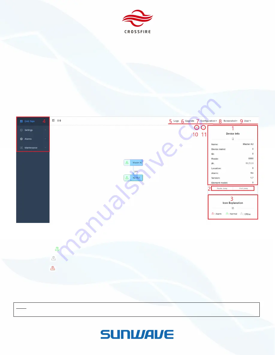
System Topology
System Topology is set as the default homepage of OMT. Using the following steps to display the System Topology:
1.
Select the DAS Topo tab.
2.
Click Refresh to display Topology.
The system topology is shown in Figure 12. The Master A2 icon is on the left of the frame as host. Lower level elements
are placed as a tree structure based on the physical optical connections. Except for the Master A2, all other slaves are
named after the optical port they are connected to.
Figure 12.
Displaying the System Topology
Device icons in the topology have 3 colors
—
green, Grey and red:
Green
icon
with green box line:
indicates this element is connected and online without alarm.
Grey
icon
with grey box line:
indicates this element was once connected but is currently disconnected.
Red
icon
with red box line:
indicates this element has an alarm.
The device icons with purple box line indicates which element’s OMT user is logged in.
When a grey icon shows up, check whether this device exists or not. If the device does not exist anymore, delete the
device in the DAS Topo page.
Note:
deleting one device or all slave devices must be under
Factory Mode
. Access
Factory Mode
through
Maintenance
-> Factory Command -> Factory Mode
. Enable the mode and click
Set
to validate it.


