background image

Installer’s Guide – (Gas Post-Boost) Solar Water Heater

4

H4110    4110    Rev. F

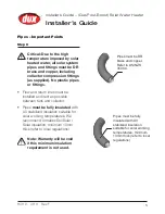
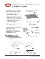
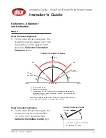
Water Connections

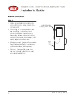
Step 5 

•  Using correct plumbing methods, 

connect the cold water pipe to the 
storage tank.

•  According to local regulations and 

the plumbing code, fit any and 
all valves that are necessary e.g. 
tempering valves, pressure limiting 
valves, line strainer, duo valves, cold 
water expansion valves etc. 

•  We recommend the use of new valves 

for all Installation. Refer to plumbing 
code and/or local requirements.

•  Connect the supplied hose from 

the top left tank outlet to the heat 
exchanger water inlet. 

Cold 

water 

inlet

Outlet to the heat 

exchanger water inlet

Installer’s Guide

Содержание D2FL20

Страница 1: ...stallation Adherence to local authority and OH S regulations Victorian PIC Requirements Installer s Guide For advice repairs and service call 1300 365 115 Australia 0800 729 389 New Zealand Important...

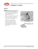
Страница 2: ...ectors Important Points 8 Collectors Attaching to Roof 9 Collectors Attaching Fittings 11 4 Way Union Assembly 14 Anti Frost Valve 15 Flashing 16 Temperature Sensor 17 Heat Trap Non Return Valve 19 PT...

Страница 3: ...leave enough length of pipe to allow easy connections 250 L 315 L 400 L Tank Height 1444 1754 1703 Overall diameter 617 617 705 A Hot water outlet 1230 1300 1450 B Tempered water outlet mid way betwe...

Страница 4: ...before you begin Safety Audit Step 2 Arrive at site park vehicle as close as allowable to installation and conduct a safety audit also known as Work Method Statements WMS or Job Site Analysis JSA Pri...

Страница 5: ...Placement of New Tank Step 4 Safely position new storage tank on a level surface in accordance with all plumbing and building regulations Note We recommend a plinth be installed under the water heater...

Страница 6: ...code fit any and all valves that are necessary e g tempering valves pressure limiting valves line strainer duo valves cold water expansion valves etc We recommend the use of new valves for all Instal...

Страница 7: ...lines must be installed as direct as possible between tank and collector Pipes must be fully insulated with UV stabilized insulation suitable for solar working temperatures We recommend Armaflex DuoSo...

Страница 8: ...tly installed and hidden inside the roof cavity if possible Take care when running flow and return lines through the roof cladding and the eaves Note Where roof and the eaves are made from asbestos sp...

Страница 9: ...ector Orientation please account for the Magnetic Declination of your geographic location Collector Inclination Guide C A C A Dux preferred range B Industry accepted range C If orientations A or B are...

Страница 10: ...pressurize them immediately after inspection Critical Do not leave collectors pressurised for longer than 24 hours To prevent damage collectors should be left pressurised only when connected to the s...

Страница 11: ...from the gutter or greater if roof allows Note Ensure that the rail is parallel with the gutter Step 10 For Metal Roofs Only Fix roofing screws through the mounting straps on both sides using rubber g...

Страница 12: ...position over the roof truss Note A minimum of 3 roofing screws of 40mm length must be used to fix the collector strap to the truss Ensure collector strap is located on truss vertically Repeat this p...

Страница 13: ...f installation hold fitting A see illustration in margin while tightening nut B to prevent twisting the header pipe Critical Do not use multi grips or similar tool as you will damage the brass fitting...

Страница 14: ...er heater Step 14 Repeat the process for the second collector Note Ensure this is done with full consideration to OH S regulations Care should be taken Step 15 Now position the top mounting rail and r...

Страница 15: ...ld pipe connects to the bottom of the collectors the solar return hot pipe connects to the top of the collectors diagonally opposite to the solar cold pipe connection We suggest when you install pipes...

Страница 16: ...sky Note If installed in top left bottom right of collector then T should be reversed When fitting the 4 Way Union assembly we recommend Loctite 577 Thread sealant and or a good quality pink teflon t...

Страница 17: ...kit form and must be ordered seperately Connect the anti frost valve to the top collector connection on the opposite collector to where the thermowell air bleed valve is installed Ensure the valve is...

Страница 18: ...Dektite or lead collars Where flow and return lines penetrate the roof surface the penetration must occur on the high side of the roof profile not in the valley Seal the roof penetration with a flexi...

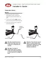
Страница 19: ...e thermowell Firmly secure the sensor using the cable securing clip Cable securing clip Collector temperature sensor Sensor secured by clip Warning Install the sensor cable such that it does not touch...

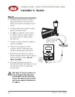
Страница 20: ...or which collector sensor cable goes into which terminal block connection Ensure terminal block is covered ideally installed within the roof space and secured to a truss Do not leave exposed If the te...

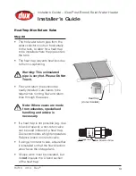
Страница 21: ...be neatly installed Care needs to be taken when running flow and return lines through the eaves Note Where eaves are made from asbestos specialised handling and advice is necessary If a heat trap is n...

Страница 22: ...e water heater gas inlet for easy connection and removal The thread diameter is R 20mm Fit an AGA approved isolating gas cock in the supply line adjacent to the water heater gas connection Ensure that...

Страница 23: ...p 25 Install a Weatherproof GPO for the system This water heater is designed for connection to the following 1 Solar Pump Module CONTINUOUS TARIFF 2 Tank Boost Off Peak single phase 240V A C supply Wa...

Страница 24: ...tep 27 Gas Fitter Test operation by lighting the water heater Check that the gas inlet and test point pressures comply with the Data Plate on the side of the gas water heater If necessary adjust accor...

Страница 25: ...e Low Burner Rate Step 29 Setting the Low Burner Rate Set the Lower Dip Switch Block label 2 for minimum output setting as shown below Open a hot water outlet fully in order to start combustion Slowly...

Страница 26: ...shown right Open a hot water outlet fully in order to start combustion Slowly rotate the maximum gas control volume screw 4 clockwise or anti clockwise until the correct high rate test point pressure...

Страница 27: ...6 Collectors aligned and attached to roof 7 11 Fittings attached to collectors 12 16 4 Way Union Assembly fitted 17 Anti Frost Valve fitted 18 Roof penetration sealed with a flexible waterproof flash...

Страница 28: ...Dux Hot Water Owner s Manual supplied with the solar water heater Upon completion of installation this document must be given to the home owner in its entirety When required by Dux Hot Water the home...

Страница 29: ...5 8 6 9 2 1 3 System Components 1 PTR valve 2 Hot water outlet to house 3 Cold water inlet 4 Solar collector return 5 Gas inlet 6 Cold water outlet to solar collector 7 Solar collector sensor lead 8...

Страница 30: ...E 1 10 DETAIL D 10 DETAIL E 13 12 11 16 15 14 System Components 1 Air bleed valve 2 Bush 3 15mm Female Tee 4 Union 15mm M 15mm C 5 Sensor Dry Well 6 Hex nipple 7 Union 1 C M 8 Union conetite DETAIL A...

Страница 31: ...13 12 11 16 15 14 A B C DETAIL A 1 2 3 4 5 6 3 7 DETAIL B 8 DETAIL C SCALE 1 10 9 DETAIL D 10 DETAIL E 13 12 11 16 15 14 C DETAIL A DETAIL C SCALE 1 10 9 DETAIL E 13 12 11 16 15 14 System Components 9...

Страница 32: ...t Boost Solar Water Heater H4110 4110 Rev F For Advice Repairs And Service Call 1300 365 115 Australia 0800 729 389 New Zealand Gas Post Boost Solar Water Heater Models D2FN26 D2FL26 D3FN26 D3FL26 D4F...

Отзывы: