background image


18 


MAINTENANCE INSTRUCTIONS 


This is general information for daily, weekly and monthly maintenance to be performed on your bike. 
   

DAILY MAINTENANCE 
 

After each exercise session, wipe down all the 
equipment: seat, frame, and handlebars. Pay 
special attention to the seat post, handlebar 
post and belt/chain guard. Sweat is very 
corrosive and may cause problems that require 
parts replacement later. 
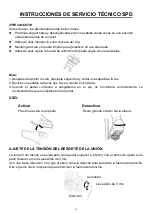
1.  Get on the bike and engage the drive train. 
2.  Pay attention to any vibrations felt through 

the pedals. If you feel any vibrations, you 
may need to tighten the pedals, bottom 
bracket, or adjust the drive belt/chain 
tension. 

3.  Use a wrench to tighten the pedals until they 

are secure.   

MONTHLY MAINTENANCE 
 

1.  Check if all hardware is secure, such as: 

water bottle holder, flywheel nuts, belt/chain 
guard bolts, brake caliper lock nuts, and 
brake caliper tension rod nuts. 

2.  Inspect the brake tension rod for signs of 

wear such as missing threads. Clean and 
lubricate the brake tension rod. 

3.  Clean and lubricate the seat post, handlebar 

post and seat slider. Remove any buildup of 
foreign material. 


WEEKLY MAINTENANCE 
 

1.  Inspect moving parts and tighten the 

hardware.   

2.  Inspect pull pin frame fittings to make sure 

the fittings are snug. Loose frame fittings 
may strip out threads over time and cause 
extensive damage. 

3.  Clean and lubricate pop pin assemblies. Pull 

on the pin and spray a small amount of 
lubricant onto the shaft.   

4.  Tighten the seat hardware to make sure the 

seat is level and centered. 

5.  Brush and treat the resistance pads. 

Remove any foreign material that may have 
collected on the pads. Spray the pads with 
silicone lubricant. This helps to reduce noise 
from friction between the pads and the 
flywheel. 

6.  Visually inspect the bottom bracket, toe clips 

and toe straps. If any of them are loose or 
disconnected, attach and tighten. 

LEATHER BRAKE PAD CARE (If applicable) 
 

1.  Perform this maintenance when the brake 

pad is first installed and for the life of the 
brake pad. Following these simple 
guidelines can increase the life of your brake 
pads. 

2.  Some brake pad assemblies are pre-

lubricated. Squeeze the brake pad. If 
lubricant is released, then the pad has been 
pre-lubricated. 

3.  If the brake pad is dry, then coat the brake 

pad with 3-n-1 oil. Brush the leather with a 
clean, wire bristle brush, and then apply the 
oil. The oil should be allowed to soak into the 
pad. Repeat 4-5 times until the pad is 
saturated, but not dripping with oil. When the 
pad is saturated, it will no longer absorb oil. 

4.  Inspect the brake pad weekly and lubricate 

if needed. The pad should not have a glazed 
appearance. If the pad appears glazed, then 
brush it with wire brush and apply lubricant 
as needed. If any of the sponge padding is 
showing through the leather pad, the brake 
pad should be replaced. 


Version 1.4 
 

Содержание SYNERGY PRO SF-B1851

Страница 1: ...A HABERNOS CONTACTADO support sunnyhealthfitness com 1 877 90SUNNY 877 907 8669 Fran ais Page 31 42 IMPORTANT Veuillez conserver le manuel du propri taire pour les instructions de r glage et d entreti...

Страница 2: ...for commercial use INFORMACI N IMPORTANTE DE SEGURIDAD Gracias por haber elegido nuestro producto Para garantizar su seguridad y salud utilice este equipo correctamente Es importante leer todo el man...

Страница 3: ...ation commerciale WICHTIGE SICHERHEITSHINWEISE Wir danken Ihnen dass Sie sich f r unser Produkt entschieden haben Zur Gew hrleistung Ihrer Sicherheit und Gesundheit verwenden Sie dieses Ger t bitte or...

Страница 4: ...75 75 66 76 67 67 73 86 78 89 89 85 80 80 81 82 70 70 61 61 1 2 4 6 8 9 17 22 25 33 33 33 33 34 34 35 36 37 37 37 50 53 53 46 57 57 65 74 79 74 79 74 79 47 50a 50b 52 54 55 84L 84R 76 76 76 94 95 96...

Страница 5: ...n support sunnyhealthfitness com o 1 877 90SUNNY 877 907 8669 Pour commander des pi ces de rechange clients am ricains et canadiens seulement Veuillez fournir les informations suivantes afin que nous...

Страница 6: ...crew M5 10 4 24 Right Belt Cover 1 71 Spring Washer 6 1 9 3 t1 6 1 25 Front Cover 1 72 Spring Washer 5 1 7 7 t1 3 3 26 Crank Cover 1 73 Hex Flange Nut M12 1 0P 1 27 Magnet Plate Cover 2 74 Flat Washer...

Страница 7: ...Izquierda 1 70 Tornillo de Cabeza Plana M5 10 4 24 Cubierta de Cinta Derecha 1 71 Arandela El stica 6 1 9 3 t1 6 1 25 Cubierta Delantera 1 72 Arandela El stica 5 1 7 7 t1 3 3 26 Cubierta de Manivela 1...

Страница 8: ...te Cylindrique M5 10 4 24 Couverture de la Courroie de Droite 1 71 Rondelle Ressort 6 1 9 3 t1 6 1 25 Cache Avant 1 72 Rondelle Ressort 5 1 7 7 t1 3 3 26 Carter de Manivelle 1 73 crou Hexagonal Embas...

Страница 9: ...echte Riemenabdeckung 1 71 Federscheibe 6 1 9 3 t1 6 1 25 Frontabdeckung 1 72 Federscheibe 5 1 7 7 t1 3 3 26 Kurbelabdeckung 1 73 Sechskant Flanschmutter M12 1 0P 1 27 Magnetplatten Abdeckung 2 74 Unt...

Страница 10: ...Unscrew 4 Hex Socket Head Bolts No 75 from Main Frame No 1 with Allen Wrench No 95 Remove 4 Flat Washers No 90 the Rear Shipping Tube No 93 and Front Shipping Tube No 92 from Main Frame No 1 You may...

Страница 11: ...tightening the Adjustment Knob No 22 Attach Handlebar No 9 onto Handlebar Post No 4 with 2 Hex Socket Head Bolts No 91 and 2 Flat Washers No 90 Secure and tighten with Allen Wrench No 95 Insert Compu...

Страница 12: ...nk No 14L at 90 Turn the pedal bolt on the Left Pedal No 15L COUNTER CLOCKWISE as tightly as you can with your hand Then use Spanner No 94 to tighten and secure Turn the Left Nylon Nut No 84L CLOCKWIS...

Страница 13: ...he Computer No 50 The installation is complete BATTERY REPLACEMENT 1 Press the buckle of battery cover on the back of the Computer No 50 then remove battery cover 2 Remove the 2 old AAA batteries in t...

Страница 14: ...tance of the bike using the Tension Control Knob No 21 Increase the level of resistance by turning the Tension Control Knob No 21 to the RIGHT clockwise decrease the level of resistance by turning the...

Страница 15: ...No 22 to secure it Next stand at the front of the bike so that you re directly in front of the handlebar Firmly grasp and hold each side of the Handlebar No 9 place one foot on the Front Stabilizer N...

Страница 16: ...a time 2 Check your pedals each time before you ride the bike 3 When the pedal starts to wear on the axle it will not function properly We recommend you replace the entire pedal USE Engaging Disengagi...

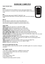
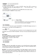
Страница 17: ...average cadence RPM in STOP mode MAX CADENCE MAX RPM Displays the maximum cadence RPM in STOP mode DISTANCE DIST Accumulates total distance from 0 0 to 999 9 KM or Miles User can preset TARGET DISTANC...

Страница 18: ...CE MODE Press and hold MODE for 2 seconds to enter RACE mode In RACE MODE only TIME and DIST can be set Default values for 10 minutes 4 KM or Miles Total is 10 bars PULSE To measure the pulse press MO...

Страница 19: ...amage 3 Clean and lubricate pop pin assemblies Pull on the pin and spray a small amount of lubricant onto the shaft 4 Tighten the seat hardware to make sure the seat is level and centered 5 Brush and...

Страница 20: ...4 Pernos de Cabeza Hueca Hexagonal n 75 de la Estructura Principal n 1 con la Llave Allen n 95 Retire 4 Arandelas Planas n 90 el Tubo de Env o Posterior n 93 y el Tubo de Env o Frontal n 92 de la Estr...

Страница 21: ...Ajuste n 22 Fije el Manubrio n 9 al Barral del Manubrio n 4 con 2 Pernos de Cabeza Hueca Hexagonal n 91 y 2 Arandelas Planas n 90 Asegure y apriete con la Llave Allen n 95 Inserte la Computadora n 50...

Страница 22: ...no del pedal en el Pedal Izquierdo n 15L HACIA LA IZQUIERDA lo m s fuerte que pueda con la mano Luego use la Llave Inglesa n 94 para apretar y asegurar Gire la Tuerca de Nailon Izquierda n 84L HACIA L...

Страница 23: ...utadora n 50 La instalaci n est completa CAMBIO DE PILAS 1 Presione el broche de la cubierta de las pilas en la parte posterior de la Computadora n 50 luego retire la cubierta de las pilas 2 Retire la...

Страница 24: ...Almohadilla de Ajuste de Apoyo n 37 vuelva a apretar la Tuerca Delgada Hexagonal n 76 gir ndola hacia la izquierda direcci n B para completar el ajuste del equilibrio de la bicicleta Si es necesario r...

Страница 25: ...asegurar el Deslizante del Asiento n 8 en su lugar 22 9 AJUSTE DEL MANUBRIO Es importante que tanto el manubrio como el asiento est n fijados a la altura correcta de su cuerpo Para ajustar la altura d...

Страница 26: ...o con facilidad NOTA Tenga siempre cuidado al mover la bicicleta Un impacto inesperado como dejar caer la bicicleta puede causar lesiones y afectar el funcionamiento de la bicicleta DESMONTAJE Para su...

Страница 27: ...atilla a la vez 2 Revise sus pedales cada vez que vaya a montar en bicicleta 3 Cuando el pedal comience a desgastarse en el eje no funcionar correctamente Le recomendamos que reemplace todo el pedal U...

Страница 28: ...DA CADENCE RPM CADENCIA Muestra la frecuencia por minuto de 0 a 999 AVG CADENCE AVG RPM CADENCIA MEDIA Muestra la cadencia media RPM en el modo STOP PARADA MAX CADENCE MAX RPM CADENCIA M XIMA Muestra...

Страница 29: ...ETIVO Presione SET CONFIGURACI N para aumentar la CADENCE CADENCIA cinco a la vez El cambio de ajuste es 15 20 110 115 120 15 20 115 120 15 20 3 El rango de ajuste de 15 120 el valor predeterminado es...

Страница 30: ...utadora est en la funci n PULSE PULSO Sostenga el sensor de pulso del manubrio durante al menos 5 segundos para medir su pulso Este valor es solo de referencia No se puede utilizar como base para un t...

Страница 31: ...empo y causar da os considerables 3 Limpie y lubrique los ensambles del resorte de regulaci n Tire de la clavija y roc e una peque a cantidad de lubricante en el eje 4 Ajuste las piezas met licas del...

Страница 32: ...TAPE 1 D visser les 4 Boulons T te Hexagonale N 75 du Cadre Principal N 1 avec Cl Allen N 95 Retirer les 4 Rondelles Plates N 90 le Tube D exp dition Arri re N 93 et le Tube D exp dition Avant N 92 d...

Страница 33: ...en resserrant le Bouton de R glage N 22 Fixer le Guidon N 9 la Tige de Guidon N 4 avec 2 Boulons T te Hexagonale N 91 et 2 Rondelles Plates N 90 Fixer et serrer avec la Cl Allen N 95 Mettre l Ordinate...

Страница 34: ...14L Serrer avec la main le boulon sur la P dale Gauche N 15L DANS LE SENS ANTIHORAIRE aussi fermement que possible Puis avec la Cl Tricoise N 94 resserrer davantage si n cessaire Serrer avec la main...

Страница 35: ...on est termin e REMPLACEMENT DES PILES 1 Appuyer sur le fermoir du couvercle du compartiment piles situ l arri re de l Ordinateur N 50 et retirer le couvercle 2 Retirer les 2 anciennes piles du compar...

Страница 36: ...e r glage du P dale de R glable N 37 termin resserrer l crou Hexagonal Mince N 76 en le tournant dans le sens antihoraire direction B pour achever le r glage de l quilibre du v lo Si n cessaire r p te...

Страница 37: ...glage N 22 pour immobiliser le Glissoir de Selle N 8 22 9 R GLAGE DU GUIDON Il faut que le guidon et la selle soient tous deux r gl s la hauteur adapt e votre corps Pour r gler la hauteur du guidon d...

Страница 38: ...tendu tel que la chute du v lo peut tre l origine de blessures et de probl mes de fonctionnement du v lo DESCENTE Pour votre s curit il est recommand de ne jamais tenter de descendre ou de retirer les...

Страница 39: ...pied la fois 2 V rifiez vos p dales chaque fois avant de faire du v lo 3 Lorsque la p dale commence s user au niveau de l axe elle ne peut plus fonctionner correctement Nous vous recommandons de rempl...

Страница 40: ...iche la vitesse maximale uniquement en mode STOP ARR T CADENCE TR MIN Affiche la fr quence par minute de 0 999 AVG CADENCE CADENCE MOYENNE EN TR MIN Affiche la cadence moyenne TR MIN uniquement en mod...

Страница 41: ...R CIBLE Appuyer sur la touche SET R GLER pour augmenter la CADENCE TR MIN de cinq en cinq Les modifications de r glage sont 15 20 110 115 120 15 20 115 120 15 20 3 La plage de r glage est de 15 120 la...

Страница 42: ...POULS Appuyer sur le capteur de pouls de la poign e pendant au moins 5 secondes pour mesurer votre pouls Cette valeur est uniquement indicative Elle ne constitue pas un l ment de r f rence pour un tra...

Страница 43: ...mager le filetage et de causer des dommages importants 3 Nettoyez et lubrifiez les assemblages de bouton cliquet Tirez sur le bouton et pulv risez une petite quantit de lubrifiant sur l arbre 4 Serrez...

Страница 44: ...Innensechskantbolzen Nr 75 mit dem Inbusschl ssel Nr 95 vom Hauptrahmen Nr 1 Entfernen Sie 4 Unterlegscheiben Nr 90 die Hintere Versandh lse Nr 93 und die Vordere Versandh lse Nr 92 vom Hauptrahmen N...

Страница 45: ...und festziehen Befestigen Sie die Lenkstange Nr 9 mit 2 Innensechskantbolzen Nr 91 und 2 Unterlegscheiben Nr 90 an der Lenkerst tze Nr 4 Mit dem Inbusschl ssel Nr 95 festdrehen und sichern Setzen Sie...

Страница 46: ...be am Linke Pedal Nr 15L GEGEN DEN UHRZEIGERSINN mit der Hand so fest wie m glich an Anschlie end mit dem Schraubenschl ssel Nr 94 festdrehen und sichern Drehen Sie die Linke Nylonmutter Nr 84L IM UHR...

Страница 47: ...Batterien ist abgeschlossen AUSTAUSCHEN DER BATTERIEN 1 Dr cken Sie die Verschlusskappe der Batterieabdeckung auf der R ckseite des Computer Nr 50 und entfernen Sie dann die Batterieabdeckung 2 Entfer...

Страница 48: ...g der Einstell Fu polster Nr 37 fertig sind ziehen Sie die Flache Sechskantmutter Nr 76 durch Drehen gegen den Uhrzeigersinn Richtung B wieder fest Damit ist die Balanceeinstellung des Fahrrads abgesc...

Страница 49: ...Position zu fixieren 22 9 EINSTELLEN DER LENKSTANGE Es ist wichtig dass die Lenkstange und der Sitz auf die richtige H he im Verh ltnis zu Ihrem K rper eingestellt sind Um die H he der Lenkstange einz...

Страница 50: ...eien Sie immer vorsichtig wenn Sie das Fahrrad bewegen Unerwartete St e wie z B ein Fallenlassen des Fahrrads k nnen zu Verletzungen f hren und die Funktion des Fahrrads beeintr chtigen ABSTEIGEN Aus...

Страница 51: ...dem anderen 2 Kontrollieren Sie Ihre Pedale vor jedem Einsatz 3 Wenn das Pedal an der Achse zu verschlei en beginnt ist die einwandfreie Funktion nicht mehr gew hrleistet Wir empfehlen das gesamte Pe...

Страница 52: ...P Modus an MAX CADENCE MAX RPM Zeigt die maximale Trittfrequenz RPM im STOP Modus an DISTANCE DIST DISTANZ Akkumuliert die Gesamtdistanz von 0 0 bis 999 9 KM oder Meilen Der Benutzer kann TARGET DISTA...

Страница 53: ...iese Taste 2 Sekunden lang gedr ckt um den RACE Modus aufzurufen Im RACE MODE k nnen nur TIME ZEIT und DIST DISTANZ eingestellt werden Standardwerte f r 10 Minuten 4 KM oder Meilen Insgesamt sind es 1...

Страница 54: ...n und schmieren Sie die Pop Pin Einheiten Ziehen Sie den Pin an und spr hen Sie eine kleine Menge Schmiermittel auf den Schaft 4 Ziehen Sie die Sitzbefestigungen fest und vergewissern Sie sich dass de...

Страница 55: ......
Отзывы: