background image


PARTS LIST 


No. 

Description 

Spec.  Qty.    No. 

Description 

Spec. 

Qty. 

Main Frame 


39 

Rotary Knob Top Cover 


Base Frame 


40 

Rotary Knob Bottom Cover   

Left Upright Tube 


41 

Computer Bottom Wire 


Right Upright Tube 


42 

Computer Top Wire 


DC Motor 


43 

Ring Wire Protector B 


Computer Tube 


44 

Magnetic Ring 


Left Handlebar 


45 

Blue Single Wire 


Right Handlebar 


46 

Ring Wire Protector A 


Front Roller 


47 

Strengthen Tube Cushion 


10 

Back Roller 


48 

Isolation Nylon Pad 


11 

Wire Clip 


49 

Running Board Tube 


12 

Allen Wrench 

S5 


50 

Cushion 


13 

Safety Key 


51 

Spring   


14 

Adjustable Foot Pad 


52 

Brown Single Wire 


15 

Running Board 


53 

Grounding Wire 


16 

Moving Wheel 


54 

Single Wire 


17 

Motor Front Cover 


55 

Tablet Bracket Base 


18 

Motor Top Cover 


56 

Rubber Pad 


19 

Motor Bottom Cover 


57 

Tablet Bracket Front Cover   

20 

Side Rail 


58 

Tablet Bracket Back Cover   

21 

Right Back End Cap 


59 

Mobile Cover 


22 

Left Back End Cap 


60 

Left Foam Grip 


23 

Overload Protector 


61 

Right Foam Grip 


24 

Motor Belt 


62 

Fixed Tuning Plate 


25 

Rubber Pad 


63 

Rotary Knob 


26 

Running Belt 


64 

Spring 


27 

Foot Pad 


65 

Lock Nut 

M8 

10 

28 

Computer Top Cover 


66 

Lock Nut 

M6 

29 

C-shape Foot Pad 


67 

Bolt   

M6*45 

30 

Outer Handlebar Cover 


68 

Bolt   

M8*35 

31 

Power Cord 


69 

Rubber Band 


32 

Switch   


70 

Bolt   

M6*65 

33 

Inner Handlebar Cover 


71 

Bolt   

M8*16 

34 

Computer Bottom Cover 


72 

Bolt   

M5*8 

35 

Left Upright Tube Outer 
Cover 


73 

Bolt   

M8*25 

36 

Left Upright Tube Inner 
Cover 


74 

Bolt   

M6*35 

37 

Right Upright Tube Outer 
Cover 


75 

Bolt   

M6*35 

38 

Right Upright Tube Inner 
Cover 


76 

Shoulder Screw 

M8*25 


Содержание SF-T7946

Страница 1: ...R MANUAL IMPORTANT Please retain owner s manual for maintenance and adjustment instructions Your satisfaction is very important to us PLEASE DO NOT RETURN UNTIL YOU HAVE CONTACTED US support sunnyhealthfitness com or 1 877 90SUNNY 877 907 8669 ...

Страница 2: ...To ensure safety the equipment should have at least 8 feet 240 CM of free space behind it and 2 feet 60 CM on each side Do not place the treadmill on any surface that blocks air openings To protect the floor or carpet from damage place a mat under the treadmill 5 Ensure that all nuts and bolts are securely tightened before using the equipment The safety of the equipment can only be maintained if i...

Страница 3: ...2 EXPLODED DIAGRAM ASSEMBLY CONTENTS When you open the carton you will find the below parts inside 1 63 57 95 12 13 ...

Страница 4: ... Front Cover 1 55 Tablet Bracket Base 1 18 Motor Top Cover 1 56 Rubber Pad 1 19 Motor Bottom Cover 1 57 Tablet Bracket Front Cover 1 20 Side Rail 2 58 Tablet Bracket Back Cover 1 21 Right Back End Cap 1 59 Mobile Cover 1 22 Left Back End Cap 1 60 Left Foam Grip 1 23 Overload Protector 1 61 Right Foam Grip 1 24 Motor Belt 1 62 Fixed Tuning Plate 2 25 Rubber Pad 1 63 Rotary Knob 2 26 Running Belt 1 ...

Страница 5: ... 8 5 17 2 85 Screw ST2 9 9 5 4 97 Bolt M8 55 2 86 Screw ST4 2 15 8 98 Flat Washer Φ8 24 2 2 87 Screw 2 6 6 5 99 Armrest Nylon Gasket 2 88 AC Single Wire 1 HARDWARE PACKAGE Ordering Replacement Parts U S and Canadian Customers only Please provide the following information in order for us to accurately identify the part s needed The model number found on cover of manual The product name found on cov...

Страница 6: ...and remove all contents Place the Main Frame No 1 on level ground and ensure that you have a clean adequate workspace STEP 2 Hold up the computer frame Insert the Rotary Knob No 63 to the Right Upright Tube No 4 and then screw tightly Insert the Rotary Knob No 63 to the Left Upright Tube No 3 and then screw tightly Notice If the Rotary Knob No 63 can not be screwed inside you can try to shake the ...

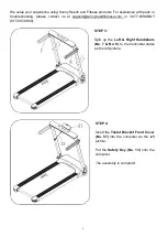
Страница 7: ...tact us at support sunnyhealthfitness com or 1 877 90SUNNY 877 907 8669 STEP 3 Spin up the Left Right Handlebars No 7 No 8 to the horizontal status as the left picture STEP 4 Insert the Tablet Bracket Front Cover No 57 into the computer as the left picture Put the Safety Key No 13 onto the computer The assembly is complete ...

Страница 8: ... or repairing the unit The following timetable is recommended Light user less than 3 hours week every 2 months Medium user 3 5 hours week every 45 days Heavy user more than 5 hours week every month NOTE To better maintain the treadmill and prolong its life it is suggested that the treadmill be powered off for 10 minutes every 2 hours and fully powered off whenever not in use A loose Running Belt N...

Страница 9: ...t the Running Belt No 26 according to instructions below with Allen Wrench No 12 If the Running Belt No 26 drifts to the left remove the Safety Key No 13 turn the adjusting bolt on the left side 1 4 turn clockwise then start running until the Running Belt No 26 is centered Refer to image B If the Running Belt No 26 drifts to the right remove the Safety Key No 13 turn the adjusting bolt on the righ...

Страница 10: ...o the main frame The folding is complete NOTE If the Rotary Knob No 63 does not move you can shake the upright tubes and the computer set then rotate Put the treadmill close to the wall to store Do not allow children to climb on treadmill UNFOLDING 1 Hold the end of the treadmill with both hands and place one foot on the Base Frame No 2 Push the treadmill forward a little using one foot to hook up...

Страница 11: ...P to support the top end of the treadmill Next place one foot at position K to hold the bottom end of the treadmill steady With your foot at K slowly tilt the top of the treadmill down Once the Main Frame P reaches a low enough point the wheels of the treadmill will touch the ground To transport hold the treadmill from position P and tilt until the wheel s K are able to move on the ground ...

Страница 12: ... with all local codes and ordinances CAUTION Improper connection of the equipment can result in risk of electric shock Check with a qualified electrician or serviceman if you are unsure whether the product has been properly grounded Do not modify the plug provided with this product If it will not fit the outlet have a proper outlet installed by a qualified electrician Ensure that the product is co...

Страница 13: ...tops IMPORTANT NOTE Pressing STOP once will pause the treadmill Current workout data will be retained You can press START to continue the workout or press STOP again to clear current workout data BUTTON Press this button to choose program from manual mode P1 P15 FAT BUTTON When the treadmill in standby state press this button to choose from the following modes manual mode time countdown mode dista...

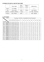
Страница 14: ... computer to stop the treadmill PRESET PROGRAMS Press the button to choose a program from P1 P12 When the program is set the time window will show the default data of TIME and flash Press the SPEED buttons to adjust the time required Each program has been divided into 20 sections each exercise time the setting time 20 Press the button and the treadmill will run at the first section speed in a 3 se...

Страница 15: ...2 5 4 3 2 P07 SPEED 2 3 3 3 4 5 3 4 5 3 4 5 3 3 3 6 6 5 3 3 P08 SPEED 2 3 3 6 5 4 4 6 2 4 6 5 4 4 4 2 3 4 4 2 P09 SPEED 2 4 4 3 5 4 3 2 4 5 6 6 4 4 4 5 6 3 3 2 P10 SPEED 2 4 5 6 3 5 4 6 3 3 6 6 5 4 4 2 4 4 3 3 P11 SPEED 2 5 4 3 4 5 6 6 4 5 6 6 5 5 6 3 5 5 4 3 P12 SPEED 3 4 5 6 5 4 5 2 5 6 4 5 5 3 6 5 5 2 6 3 P13 SPEED 3 6 2 5 5 6 6 5 5 3 3 5 2 5 6 5 6 5 4 3 P14 SPEED 2 2 4 5 6 5 4 3 2 1 2 3 4 5 6 ...

Страница 16: ...to the computer Press the button to start the treadmill The treadmill will start at the default speed of 0 5MPH Once you feel comfortable you may slowly increase the speed When you are finished with your exercise press the button or remove the magnetic end of Safety Key No 13 to stop the treadmill SAFETY LOCK Remove the Safety Key No 13 from the computer to stop the treadmill immediately All data ...

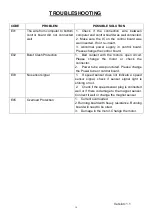
Страница 17: ...contact with the motor s open circuit Please change the motor or check the connector 2 Power tube was punctured Please change the Power tube or control board E03 No sensor signal 1 If speed sensor does not indicate a speed sensor signal check if sensor signal light is shining or not 2 Check if the speed sensor plug is connected well or if there is damage to the magnet sensor Connect it well or cha...

Страница 18: ...17 ...

Отзывы: