


12
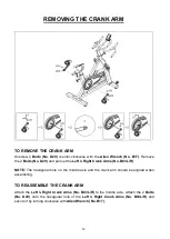
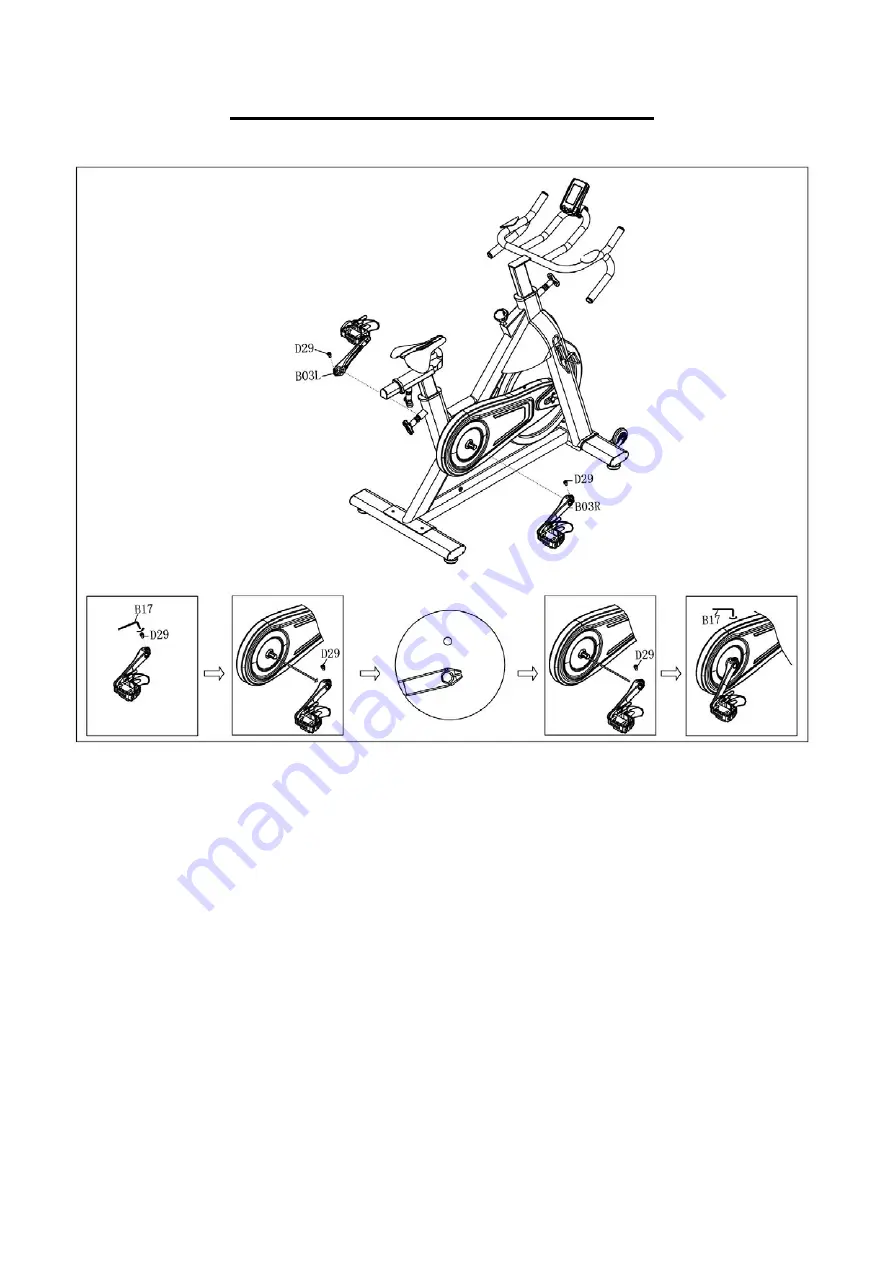
REMOVING THE CRANK ARM
TO REMOVE THE CRANK ARM
Unscrew 2
Bolts (No. D29)
counter-clockwise
with the
Allen Wrench (No. B17)
. Remove
the 2
Bolts (No. D29)
and pull out the
Left
&
Right Crank Arms (No. B03L/R)
.
NOTE:
The hexagonal hole on the middle axle and the crank arm should be aligned when
assembling.
TO REASSEMBLE THE CRANK ARM
Attach the
Left
&
Right Crank Arms (No. B03L/R)
to the middle axle. Attach the 2
Bolts
(No. D29)
onto the hexagonal hole of the
Left
&
Right Crank Arms (No. B03L/R)
and
secure it by turning
clockwise
with
Allen Wrench (No. B17)
.
Содержание SF-B1735
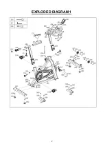
Страница 3: ...2 EXPLODED DIAGRAM 1...
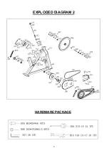
Страница 4: ...3 EXPLODED DIAGRAM 2 HARDWARE PACKAGE...
Страница 18: ......


