background image


PARTS LIST


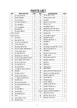
NO. 

DESCRIPTION 

QTY 


NO. 

DESCRIPTION 

QTY 

End cap F80*40 

40 

Screw 

M6*12*Φ12 

Rear stabilizer 

41 

Tension Knob  M10 

Foot levelers 

42 

Nut M10 

Washer 

d8*φ16*1.5 

43 

Brake rod  

φ10*210 

Screw M8*55 

44 

Square nut 

Front stabilizer 

45 

Nut M6*H14*S10 

Bolt M6*45 

46 

Brake board t7*138.3*28 

Bearing 608ZZ 

47 

Spring piece t1.5*110*15.5 

9L/R 

Pedal 

48 

Woolen felt 

10L/R  Crank 

49 

Screw 

M5*10*φ8.5 

11 

End cap  

50 

Bolt M6*10*S10  

12 

Nut  M10*1.25  

51 

Washer d6*

φ12*1.2 

13 

Cover for middle axle 

52 

Nut M12*1 

14 

Jump ring  d20 

53 

Nut M6 

15 

Bearing 6004-2RS 

54 

Adjusting screw M6*60*

φ

12*5 

16 

Wave washer 

d20*Φ25*0.3 

55 

Spacer φ18*φ12.2*6 

17 

Inner chain cover 

56 

Nut M12*1 

18 

Screw ST4.8*16 

57 

Spacer

Φ

18*Φ12.1*9 

19 

Middle axle 

Φ

20*190 

58 

Crank cover 

20 

Chain wheel φ225*2.5*Z52 

59 

Inertia axle φ12*162 

21 

Drive chain 1/2*1/8*104 

60 

Bearing  6001-RS 

22 

Outer chain cover 

61 

Bushing 

23 

Screw ST4.2*13 

62 

Flywheel 

24 

Screw  M6*10 

63 

Chain wheel 

25 

Transport wheel  

φ70*24 

64 

Main frame 

26 

Saddle 

65 

Spacer 20*20*75Spanner S6 

27 

Saddle column 

66 

Spring 

Φ

2.0*Φ15*54*N12 

28 

Washer d10*φ40*4 

67 

Washer  d5*φ10*1 

29 

L shape knob M10*25 

68 

Screw M5*16 

30 

Saddle post 

69 

Shipping tube 

31 

End cap PT70*30 

70 

Screw  M8*20 

32 

Bushing PT80*40*L130 

71 

Rubber pad 44*25*3 

33 

Nut M6 

72 

Washer d6*

φ16*1.2 

34 

Screw M5*10  

73 

Washer d5*

φ10*1 

35 

Handle bar 

74L/R  Nylon nut 9/16*20*H8*S22 

36 

Handlebar post 

75 

Allen wrench S6 

37 

Nut 

76 

Spanner S13-14-15 

38 

Knob M16*1.5*27 


77 

Spanner S8-14-22 

39 

Bottle holder 


Содержание SF-B1110

Страница 1: ...CLING BIKE SF B1110 USER MANUAL IMPORTANT Read all instructions carefully before using this product Retain owner s manual for future reference For customer service please contact support sunnyhealthfi...

Страница 2: ...or adult use only 4 Use the equipment on a solid flat level surface with a protective cover for your floor or carpet To ensure safety the equipment should have at least 2 feet of free space all around...

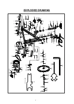
Страница 3: ...35 36 41 42 43 44 45 64 1 2 3 4 5 1 3 6 1 7 8 25 33 8 3 52 52 55 55 53 53 54 56 57 56 60 62 61 63 60 37 59 56 9R 10R 11 12 15 17 18 19 20 21 22 23 24 38 38 39 68 67 69 69 4 70 4 70 4 70 4 70 14 16 58...

Страница 4: ...r 1 56 Nut M12 1 3 18 Screw ST4 8 16 2 57 Spacer 18 12 1 9 1 19 Middle axle 20 190 1 58 Crank cover 1 20 Chain wheel 225 2 5 Z52 1 59 Inertia axle 12 162 1 21 Drive chain 1 2 1 8 104 1 60 Bearing 6001...

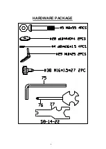
Страница 5: ...HARDWARE PACKAGE 4...
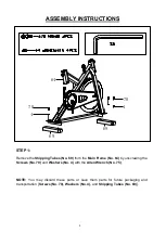
Страница 6: ...ping Tubes No 69 from the Main Frame No 64 by unscrewing the Screws No 70 and Washers No 4 with the Allen Wrench No 75 NOTE You may discard these parts or save them parts for future packaging and tran...

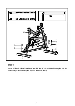
Страница 7: ...64 4 5 2 6 4 5 STEP 2 Attach the Front Rear Stabilizers No 6 No 2 onto the Main Frame No 64 and attach using 4 Hex Screws No 5 and 4 Washers No 4 6...

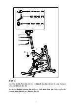
Страница 8: ...8 STEP 3 Insert the Saddle Post No 30 into the Main Frame No 64 and fix using the seat adjustment Knob No 38 Secure the Saddle Column No 27 onto the Saddle Post No 30 using the L shaped Knob No 29 and...

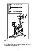
Страница 9: ...STEP 4 Insert the Handlebar Post No 36 into the Main Frame No 64 and fix with handlebar adjustment Knob No 38 Secure the Handlebar No 35 onto the Handlebar Post No 36 using the L shaped Knob No 29 an...

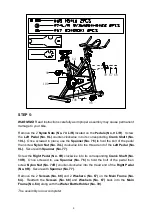
Страница 10: ...on Nut No 74L clockwise into the thread end of the Left Pedal No 9L Secure with Spanner No 77 Screw the Right Pedal No 9R clockwise into its corresponding Crank Shaft No 10R Once screwed in use Spanne...

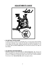
Страница 11: ...the front and rear stabilizers To do so simply rotate the Foot Levelers No 3 until the bike becomes level with the floor surface ADJUSTING THE RESISTANCE Adjust the resistance of the bike using the T...

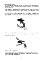
Страница 12: ...is too straight you should move the seat down 1 Loosen the seat adjustment Knob No 38 to raise or lower the Saddle Post No 30 to the desired position Make sure the Knob No 38 secures into the desired...

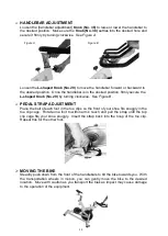
Страница 13: ...gure B PEDAL STRAP ADJUSTMENT Place the ball of each foot in the toe clips so the front of your shoe fits snuggly in the toe clip cage Rotate one foot to within arm s reach and pull the strap until th...

Отзывы: