background image


No. 

Description 

Specification 

Qty. 


No. 

Description 

Specification 

Qty. 

Base Frame 


44 

Bolt 

M8X25 

Main Frame 


45 

Bolt 

M8*15 

3L/R 

Upright Tube 


1 pr. 


46 

Bolt 

M6X18 

Console Frame 


47 

Bolt 

M8X35 

Reinforcement Tube   


48 

Bolt 

M8X60 

Incline Frame 


49 

Bolt 

M8X18 

Loudspeaker 


50 

Bolt 

M6X55 

Filter Connecting Board 


51 

Bolt 

M6X30 

Front Roller 


52 

Screw 

M5X8 

10 

Rear Roller 


53 

Screw 

M4X8 

11 

Cylinder 


54 

Screw 

ST4X32 

12 

Long Sleeve 


55 

Screw 

ST4X16 

29 

13 

Short Sleeve 


56 

Screw 

ST4X12 

14 

Running Belt 


57 

Screw 

ST2.9X9.5 

14 

15 

Running Board 


58 

Screw 

ST2.9X6 

16 

Side Rail 


59 

Bolt 

M6X12 

17 

Baffle 


60 

Washer 

Φ8X1.2 

14 

18 

Motor Cover 


61 

Washer 

Φ6X1.2 

19 

Console Upper Cover 


62 

Washer 

Φ10X1.2 

20 

Console Bottom Cover 


63 

Flat Washer 

Φ8X1.5 

21 

Console Panel 


64 

Washer 

Φ8 

22 

Panel Rear Cover 


65 

Nylon Nut 

M8 

23 

Bottle Holder 


66 

Nylon Nut 

M6 

12 

24L/R 

Base Cover 


1 pr. 


67 

Nylon Nut 

M10 

25L/R 

Rear End Cap 


1 pr. 


68 

Flat Washer 

Φ20XΦ10X2.0 

26 

Transport Wheel 


69 

Flat Washer 

Φ26XΦ8.2X2.0 

27 

Square Plug 


70 

Flat Washer 

D4 

28 

Wire Plug 


71 

Spring Washer 

D4 

29 

Power Buckle 


72 

Controller Board 


30 

Adjusting Wheel 


73 

Shortcut Key 


31 

Foot Pad 


74 

Console Linking Wire 


32 

Transport Wheel Plug 


75 

Extension Wire 


33 

Rubber Pad 


76 

Controller Wire 


34 

Oval Plug   


77 

Safety Key   


35 

Motor Belt 


78 

Light Sensor 


36 

Square Plug 


79 

Light Sensor Bracket 


37 

Foam Grip 


80 

DC Motor 


38L/R 

Anti- Slip Mat 


1 pr. 


81 

Incline Motor 


39 

Bolt 

M10X40 


82 

Switch 


40 

Bolt 

M10X20 


83 

Overload Protector 


41 

Bolt 

M10X55 


84 

Power Wire 


42 

Bolt 

M8X20 


85 

Amplifier Board 


43 

Bolt 

M8X40 


86 

Filter 


87 

Audio Jack 


89 

Allen Wrench 

S=5 

88 

MP3 Wire 


90 

Spanner 

S=13,14,15 

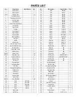
PARTS LIST 

Содержание SF-T7873

Страница 1: ...R MANUAL IMPORTANT Please retain owner s manual for maintenance and adjustment instructions Your satisfaction is very important to us PLEASE DO NOT RETURN UNTIL YOU HAVE CONTACTED US support sunnyhealthfitness com or 1 877 90SUNNY 877 907 8669 ...

Страница 2: ...carpet To ensure safety the equipment should have at least 8 feet 240 CM of free space behind it and 2 feet 60 CM on each side Do not place the treadmill on any surface that blocks air openings To protect the floor or carpet from damage place a mat under the treadmill 5 Ensure that all nuts and bolts are securely tightened before using the equipment The safety of the equipment can only be maintain...

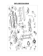
Страница 3: ...3 EXPLODED DIAGRAM ...

Страница 4: ...sher Φ8X1 5 6 21 Console Panel 1 64 Washer Φ8 6 22 Panel Rear Cover 1 65 Nylon Nut M8 8 23 Bottle Holder 2 66 Nylon Nut M6 12 24L R Base Cover 1 pr 67 Nylon Nut M10 2 25L R Rear End Cap 1 pr 68 Flat Washer Φ20XΦ10X2 0 2 26 Transport Wheel 2 69 Flat Washer Φ26XΦ8 2X2 0 4 27 Square Plug 2 70 Flat Washer D4 2 28 Wire Plug 2 71 Spring Washer D4 2 29 Power Buckle 1 72 Controller Board 1 30 Adjusting Wh...

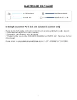
Страница 5: ...y identify the part s needed The model number found on cover of manual The product name found on cover of manual The part number found on the EXPLODED DIAGRAM and PARTS LIST found near the front of the manual Please contact us at support sunnyhealthfitness com or 1 877 90SUNNY 877 907 8669 45 M8 15 8PCS 89 S 5 1PC 60 Φ8X1 2 8PCS 90 S 13 14 15 1PC ...

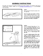
Страница 6: ...y is complete STEP 2 Hold the Console Frame No 4 Then lift up the Console Frame No 4 and Left Right Upright Tubes No 3L R together in the direction of the arrow Note Make sure you do not cut or pinch the wire inside the Right Upright Tube No 3R Fix Left Right Upright Tubes No 3L R to the Base Frame No 1 with 6 Bolts No 45 and 6 Washers No 60 using Allen Wrench No 89 Note Do not fully tighten at th...

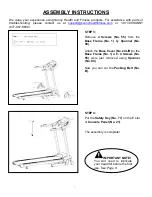
Страница 7: ...7 8669 STEP 3 Remove 4 Screws No 55 from the Base Frame No 1 by Spanner No 90 Attach the Base Cover No 24L R to the Base Frame No 1 with 4 Screws No 55 were just removed using Spanner No 90 Now you can cut the Packing Belt No B STEP 4 Put the Safety Key No 77 on the E slot of Console Panel No 21 The assembly is complete IMPORTANT NOTE You will need to lubricate your treadmill before the first use ...

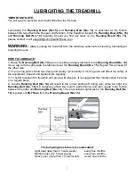
Страница 8: ...the lubricant over the Running Board No 15 Repeat this process for the other side 2 The moving parts should turn freely and quietly Abnormality of moving parts will affect the safety of the equipment Inspect and tighten bolts regularly 3 To better maintain the treadmill and prolong its lifespan it is suggested that maintenance be done on a regular basis 4 A loose Running Belt No 14 will result in ...

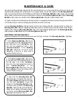
Страница 9: ...htness for the Running Belt No 14 is pulled out 50 75mm from the Running Board No 15 CENTERING THE RUNNING BELT Place the treadmill on level ground and set it at 3 5mph to check if the Running Belt No 14 drifts 1 If the Running Belt No 14 moves to the right turn the adjusting bolt on the right side turn clockwise then turn the left adjustment bolt turn counter clockwise If the Running Belt No 14 d...

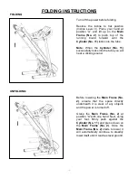
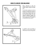
Страница 10: ...he Cylinder No 11 successfully locks into the tube you will hear a clicking sound Before lowering the Main Frame No 2 ensure that the space directly underneath it is clear of any objects and the power is turned off Grasp the Main Frame No 2 at position A with one hand Next using your foot firmly push against the Cylinder No 11 and press down on the Main Frame No 2 Once the Main Frame No 2 starts t...

Страница 11: ... the top end of the treadmill Next place one foot at position M to hold the bottom end of the treadmill steady With your foot at M slowly tilt the top of the treadmill downward towards the ground Once the treadmill reaches a low enough point the wheels of the treadmill touch the ground To transport hold the treadmill at position P and tilt until the wheels M are able to move on the ground ...

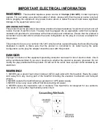
Страница 12: ... circuit and has a grounding plug that looks like the plug illustrated in sketch A Make sure that the product is connected to an outlet having the same configuration as the plug No adapter should be used with this product DANGER Improper connection of the equipment grounding conductor can result in risk of electric shock Check with a certified electrician if you are in doubt as to whether the prod...

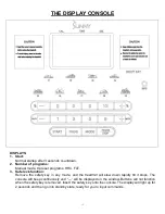
Страница 13: ...a Get to know your treadmill Before attempting to use the treadmill take some time to stand alongside and familiarize yourself with the controls 1 Turn on the power switch 2 Once you get on you can stand with your feet on the side rails and stabilize yourself by holding onto the handrails 3 Next attach the clip end of the Safety Key to your clothes and insert the magnetic end of the key into the c...

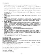
Страница 14: ...n Remove the safety key in any mode and the treadmill will slow down rapidly till it stops The console will beep continuously and will be displayed on the window Buttons will not function when the safety key is removed Insert the safety key onto the console The display will light up for 2 seconds and then go into standby state ready for you to input commands ...

Страница 15: ...es or decreases in increment of 0 1 KM time or 0 1MI time After holding for more than 2 seconds automatic continuous acceleration and deceleration will be realized The default speed is 0 6 MPH 1 0 KMH Max operating speed is 11 MPH 18 KMH 6 SPEED SHORTCUT KEYS on the handrail Press to select 1MPH 3MPH 5MPH and 9MPH when the treadmill is running 7 INCLINE INCLINE When the motor is running press to i...

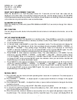
Страница 16: ...untdown mode b Press MODE to enter distance countdown mode The initial distance is 1 00 KM MI Set the distance by pressing SPEED SPEED or INCLINE INCLINE Distance setting range 1 0 99 0 KM MI Value is in increment of 1 KM MI Press START to start the treadmill If you do not press START and you press MODE again the distance value you set will be cleared and treadmill will go into calorie countdown m...

Страница 17: ...e when switching from one section to another 8 When the set time goes to zero the treadmill will slow to a stop The console will beep until the treadmill stops The screen will display END All values go to zero and treadmill is now in standby state 8 At any time if you need to stop the treadmill immediately remove the safety key LCD window will display and the console will beep three times PROGRAM ...

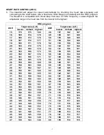
Страница 18: ... 175 53 132 137 142 21 164 169 174 54 131 136 141 22 163 168 173 55 130 135 140 23 162 167 172 56 129 134 139 24 161 166 171 57 128 133 138 25 160 165 170 58 127 132 137 26 159 164 169 59 126 131 136 27 158 163 168 60 125 130 135 28 157 162 167 61 124 129 134 29 156 161 166 62 123 128 133 30 155 160 165 63 122 127 132 31 154 159 164 64 121 126 131 32 153 158 163 65 120 125 130 33 152 157 162 66 11...

Страница 19: ... treadmill will beep every second a When the treadmill cannot detect the heart rate twice in a row b When heart rate exceeds value of 220 minus age 5 HRC does not automatically adjust the incline based on the heart rate Incline level can be adjusted manually BODY FAT TEST 1 In standby state press PROG to enter FAT Physical fitness test program 2 Press MODE to enter the program of F 1 F 2 F 3 F 4 F...

Страница 20: ...or generated by the controller if yes it means that IGBT has been broken down to cause short circuit then replace the controller E03 No sensory signal Check whether the photoelectric sensor directs to the hole on CD check whether wires of photoelectric sensor are damaged and whether terminals of the photoelectric sensor and speed terminals on the controller are firmly connected E04 Lifting learnin...

Страница 21: ...k the power supply switch over load protector and the controller s power cord and transformer to ensure well connection 3 Check whether the power cords from the electronic meter to the controller are well collected dismantle the pillar to check connecting joints on each section of the wiring from the electronic meter to the controller ensure that each wire core is well connected or the reason may ...

Отзывы: