Sunnen SV-2460 Скачать руководство пользователя страница 1

SUNNEN

®

PRODUCTS COMPANY • 7910 MANCHESTER ROAD • ST. LOUIS, MO 63143, U.S.A. • PHONE: 314-781-2100

READ THE FOLLOWING INSTRUCTIONS THOROUGHLY AND CAREFULLY BEFORE UNPACKING,
INSPECTING, OR INSTALLING THE SUNNEN

®

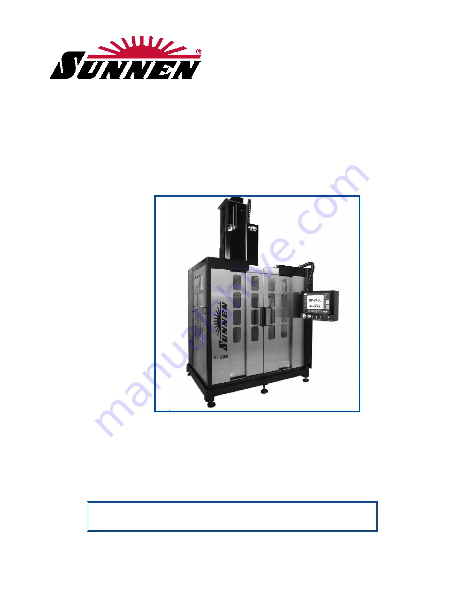
SV-2460 VERTICAL HONING MACHINE.

I-SV-461

Installation, Setup

and Operation

INSTRUCTIONS

for

SUNNEN

®

VERTICAL HONING MACHINE

Models: 

SV-2460 

“SUNNEN

®

AND THE SUNNEN LOGO ARE REGISTERED TRADEMARKS OF SUNNEN PRODUCTS COMPANY.” 

O R I G I N A L   I N S T R U C T I O N S

Содержание SV-2460

Страница 1: ...HLY AND CAREFULLY BEFORE UNPACKING INSPECTING OR INSTALLING THE SUNNEN SV 2460 VERTICAL HONING MACHINE I SV 461 Installation Setup and Operation INSTRUCTIONS for SUNNEN VERTICAL HONING MACHINE Models...

Страница 2: ...ive and motor grounding Use of any optional devices equipment between the Drive motor output chokes etc For fast service on your orders call Sunnen Automotive Customer Service toll free at 1 800 772 2...

Страница 3: ...DY THEREFORE SHALL IN ALL EVENTS BE LIMITED IN AMOUNT TO THE PURCHASE PRICE OF THAT PORTION OF THE PRODUCTS WITH RESPECT TO WHICH A VALID CLAIM IS MADE Shipping Damages Except in the case of F O B Buy...

Страница 4: ...tempt any repair or maintenance procedure beyond those described in this book Contact your Sunnen Field Service Engineer or Technical Services Representative for repairs not covered in these instructi...

Страница 5: ...k 7 SECTION 2 PREPARING FOR OPERATION General 9 Major Components 9 Operator Controls 11 Safety Symbols 11 Workholding Fixture 11 Honing Tool 11 Honing Tool Setup 12 SECTION 3 SETUP OPERATION General 1...

Страница 6: ...indows Work Area View A 3 4047 W x 4824 D x 4400 H mm 159 x 190 x 173 in Floor Space Machine Foot Print 2523 W x 2563 D x4375 H mm w o Optional Coolant System 99 x 101 x 172in Floor Weight Dry 5620 kg...

Страница 7: ...e to staging unpacking area 2 Remove plastic wrap 3 Remove top and sides from packing crate 4 Remove all loose components from crate 5 Check all components against packing list 6 Inspect Machine and c...

Страница 8: ...ble until it just touches the floor Move to rear of table and check rear of table left to right for level Adjusting Leveling Bolt in which ever of the feet is lowest as required until table base is wi...

Страница 9: ...rding and Hardware aside for reinstallation after column is installed Install Column 16 Obtain Fork Lift with required vertical movement and lift capacity to lift Column into position on Riser Weldmen...

Страница 10: ...ng 30 Reinstall Right Rear Guarding and Conduit Hangers 31 Reposition Wiring Conduit in Hangers and secure 32 Install Linear Rail Cover on front of Spindle Assembly Two 2 Access Holes are provided on...

Страница 11: ...lectrician in accordance with all local state and federal codes and regulations FAILURE TO COMPLY CAN RESULT IN PERSONAL INJURY AND DAMAGE TO THE MACHINE WARNING All wiring and electrical equipment se...

Страница 12: ...closure WARNING You must use the hole provided Drilling any new holes in the electrical enclosure may void the warranty 4 Remove hole plug located on top left side of the enclosure Then install an oil...

Страница 13: ...f metal residue it is recommended that you employ either or both a magnetic separator and filter system Check with your local Sunnen Field Service Engineer or Sunnen Products Company Technical Service...

Страница 14: ...8 NOTES...

Страница 15: ...n rear of column 3a The Operator Station houses all electronic hardware and software for hone control It is also main operator interface with machine 4a The Spindle Carriage is mounted on 9 FIGURE 2 1...

Страница 16: ...or right on models equipped with optional carriage servo motor E STOP Shuts OFF all power to the machine functions Button must release before Power ON button Pushbutton Red can be pushed CYCLE START...

Страница 17: ...NG TOOL Refer to Sunnen Industrial or Automotive Honing Supplies Catalogs for all your honing needs CAUTION Use of tooling other than Sunnen tooling will render all of features of computerized honing...

Страница 18: ...uld be 90 to left of set screw 8 Push mandrel up into Adapter until it bottoms rotate it 1 4 turn to right and push up until it bottoms again 9 Tighten Set Screw securely with chuck wrench CV CK Serie...

Страница 19: ...eral 2 using procedure above 12 Insert shimmed Main Guide beneath numeral 3 on Hone Body 13 Place shimmed Centering Guide beneath numeral 4 on Hone Body Alignment Guide NOTE DO NOT use alignment guide...

Страница 20: ...holders and repeat step 2 until the hone head is loaded with plates and holders 4 Once all plates and holders are loaded in head expand and retract holders in head several times to ensure all moving p...

Страница 21: ...versal joint see Figure 2 14 Grab spring on bottom of hone head in between mounting clips and pull it over spring slots in bottom of stone brush set using GH 50 Thumb Spring Tool refer to Figure 2 14...

Страница 22: ...16 NOTES...

Страница 23: ...its intended use Using these Machines for other purposes could result in damage to machine and loss of warranty Be sure to work in a well lit area and to use light supplied to avoid dangerous unseen c...

Страница 24: ...characteristics There are three displays that are available to operator First is BORE PROFILE This display shows a picture of load vs stroke position through bore In most cases it will display conditi...

Страница 25: ...new tool 13 Press NEXT and follow directions on display screen 14 Once Tool is installed press NEXT and then press YES on the window that says Teach Tool Size Snug 15 Set tool SNUG diameter by moving...

Страница 26: ...20 NOTES...

Страница 27: ...ease reservoir System is equipped with a Pressure Switch which flashes a warning on the operator display screen when the level pressure drops below minimum requirement To bleed system proceed as follo...

Страница 28: ...attempting to tighten these screws Examine the way covers for breaks or tears Replace as needed Every 10 000 km of Carriage Travel NOTE The control system records cumulative carriage travel If your a...

Страница 29: ...lt 6 Use tension Setscrew against Bracket to tension belt before tightening Screws on Spindle Motor Bracket New Belt Tension belt so that deflection at midway between pulleys is approximately 7 5mm 3i...

Страница 30: ...hen there is a noticeable drop in air pressure To clean or replace the Filter Element proceed as follows see Figure 4 9 1 Turn OFF power to Machine at Master ON OFF Switch Electrical Enclosure 2 Turn...

Страница 31: ...imum control of the bore diameter inspect Pneumatic Lines airlines and Fittings running to tool monthly for leaks or damaged parts Replace parts as required see Figure 4 10 25 FIGURE 4 9 Pneumatic Lin...

Страница 32: ...26 NOTES...

Страница 33: ...4 Inadequate tool s rpm A Increase tool s rpm 3 Run Diagnostic 5 Improper or diluted coolant A Check coolant 4 Poor stone life 1 Excessive tool feed rate A Decrease feed rate 2 3 Run Diagnostic 2 Inad...

Страница 34: ...y Aligned A Adjust Fixture 2 Setup Waviness 1 Improper tool length A Use tool with sufficient 2 Setup stone length to bridge waviness in bore Rainbow 1 Improper tool length A Replace tool 2 Setup tool...

Страница 35: ...those 100 cycles then the air has been successfully bled out of the system PROBLEM Routine inspection of lubrication system shows that grease is not coming out of one or more grease lines SOLUTIONS R...

Страница 36: ...30 NOTES...

Страница 37: ...NETIC SEPARATOR MACHINE RESERVOIR FLOW CONTROL ON OFF VALVE SUMP PUMP FILTERED FLUID WORKPIECE OPTIONAL COOLANT SYSTEM with PAPER FILTER A COOLANT SYSTEM OPT OPTIONAL COOLANT SYSTEM with MAGNETIC SEPA...

Страница 38: ...32 NOTES...

Страница 39: ...33 FLOW DIAGRAM B GREASE PUMP FIGURE B 1 Grease Lubrication System Flow Diagram LUBRICATOR HOUSING FILLER PORT TO BALLSCREW STROKER TO BALLSPLINE STROKER...

Страница 40: ...34 NOTES...

Страница 41: ...1 OF 2 C DECLARATION OF CONFORMITY 35 SAMPLE CE DOCUMENT...

Страница 42: ...2 OF 2 C DECLARATION OF CONFORMITY 36 SAMPLE CE DOCUMENT...

Страница 43: ...ly Be sure to read and follow instructions for operation of equipment WARNING An Arc Flash Hazard Exists Follow safe work practices and wear appropriate Personal Protective Equipment Follow proper loc...

Страница 44: ...25 4000 1 1 16 1 062500 26 9880 FORMULAS MULTIPLY BY TO GET MULTIPLY BY TO GET INCHES in x 25 4 MILLIMETERS mm MILLIMETERS mm x 0 03937 INCHES in FEET ft x 0 3048 METERS m METERS m x 3 281 FEET ft PR...

Отзывы: