background image

“Take main screen as sample”

Product Introduction

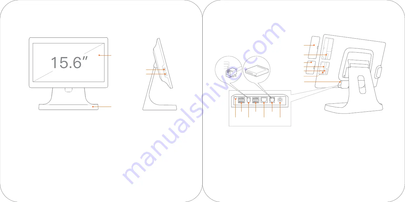
Display

Metal Base

USB interface

Power, Pilot Light

Card slot cover

USB Interface

For external keyboard, mouse and USB drive.

Display

For the touch screen used by the operator.

Metal Base

For supporting the display when put on the

desktop.

Able to be replaced with the VESA suspension

bracket.

Slot reader interface

For external MSR/RFID POS

Card slot is an optional part which may not

be available in all configurations.

TF card slot

For external TF card.

Micro USB debug port, debug key

For device debugging only.

Cash drawer interface

For external cash drawer with 120ms 

electric pulse output. No continuous power 

is supplied. This system only supports 

24V/1A cash drawers. Connecting a 12V 

drawer may result in hardware failure. 

Slot reader interface

Interface cover

TF card slot

Micro USB debug port

Port cover

Debug key

Power

  port

Headset

jack

Cash drawer

  interface

   LAN

interface

   USB

interface

   Serial

 interface 

USB

interface

GND

RXD

TXD

5V

Power

In the state of power off, a short press turns on the 

POS machine.

When powered on, press on the power button for two or 

three seconds to choose power off or restart.

If the system is frozen, press the power button for 

11 seconds to power off.

Pilot Light 

The light will be blue when the power is on. When the 

power is off, the light is off.

Содержание T2 LITE

Страница 1: ...This Manual shall be read carefully before use and remain in safe hands POS User Manual T2 LITE...

Страница 2: ...n T3522 15 6 main screen 15 6 customer screen T3523 1 Rotate the display to horizontal 2 Open the port cover 3 Connect the power interface of the adapter to the power port at the bottom of the mainfra...

Страница 3: ...Cash drawer interface For external cash drawer with 120ms electric pulse output No continuous power is supplied This system only supports 24V 1A cash drawers Connecting a 12V drawer may result in hard...

Страница 4: ...r and complete the removal of base Install VESA accessories 1 Place the VESA bracket aligning the four screw holes according to directions 2 Use the four M4 screws removed from the base to x the VESA...

Страница 5: ...ead the built in Help APP for more help Only a few steps to turn on the intelligent business equipment Press the power button and the screen will power on Enter the rst start up screen and follow the...

Страница 6: ...d the le concerning details may raise due to product updates Please be subject to the material object The company reserves the right to interpret the le and the right to revise this manual without pri...

Страница 7: ...e the receiving antenna Increase the separation between the equipment and receiver Connect the equipment into an outlet on a circuit di erent from that to which the receiver is connected Consult the d...

Отзывы: