background image

15

5.3

Communication Connection

5.3.1 Ethernet Communication Connection

Devicecan be connected to external equipment, such as PCS (power conversion

system) or EMS (energy management system) and other equipment.

step 1

Insert one end of the network cable (within the scope of delivery) to the Ethernet port of
the Ethernet switch and the other end to the port ETH2 of the device.

step 2

Configure the network parameters.

-- -- E

En

nd

d

IP addresses of ETH1 and ETH2 cannot be on the same network segment.

Otherwise, communication error occurs.

Default IP address of ETH1 is 192.168.0.100。

Default IP address of ETH2 is 192.168.1.100。

ETH2 is used by default to set the WEB of the device, and the IP address

cannot activate the DHCP function.

5.4

Earthing Connection

The grounding cable should be grounded reliably. Otherwise,

lethal electric shock may occur in case of fault; and

the device may be damaged due to lightning.

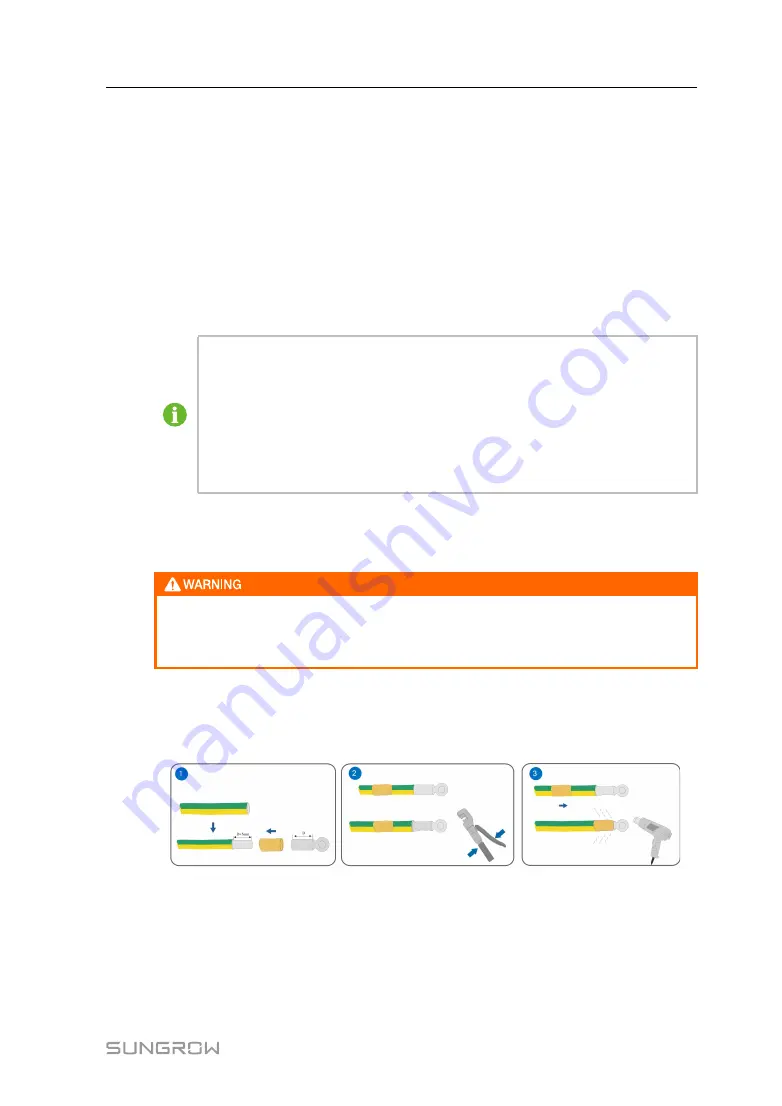
step 1

Strip the protection layer and insulation layer of the 1.5~4mm

2

/12AWG~15AWG

grounding cable by specific length, as shown in the figure below.

step 2

Crimp the stripped cable into an appropriate euro style terminal.

step 3

Secure the grounding cable to the grounding hole of the device, as shown in the figure
below.

User Manual

5 Electrical Connection

Содержание BSC200

Страница 1: ...m C Co on nt tr ro olllle er rU Us se er r M Ma an nu ua allB BS SC C2 20 00 0 U UE EN N V Ve er r1 10 0 2 20 02 22 20 01 1 BSC200 UEN Ver10 202201 BSC200 B Ba at tt te er ry y S Sy ys st te em m C C...

Страница 2: ......

Страница 3: ...ks used in this manual are owned by SUNGROW All other trademarks or registered trademarks mentioned in this manual are owned by their respective owners S So of ft tw wa ar re e L Liic ce en ns se es s...

Страница 4: ...n nu ua all Read the manual and other related documents before performing any work on the product Documents must be stored carefully and be available at all times Contents may be periodically updated...

Страница 5: ...ave time N No ot te e In order to provide customers with the best usage experience the products and product manuals are always in the process of improvement and upgrade If the manual received is sligh...

Страница 6: ......

Страница 7: ...dentifying the Device 6 3 3 Checking upon Receiving 6 3 4 Storage 7 4 Mechanical Mounting 8 4 1 Location Selection 8 4 2 Installation Tools 9 4 3 Installing the Device 9 4 3 1 Wall Mounted Installatio...

Страница 8: ...Cooling Unit Parameters 23 7 7 View History Records 23 7 7 1 View Event Records 23 7 7 2 Fault Records 23 7 7 3 Alarm Records 24 7 7 4 Running Records 24 7 7 5 Rack Records 24 7 8 Version Information...

Страница 9: ...device read these symbols carefully 1 1 Before Installation After receiving the device check whether the device is damaged due to transport Should there be any problem please contact us or the forward...

Страница 10: ...ical connection disconnect input switches upstream and ensure that the device is voltage free 1 3 Maintenance and Replacement Only persons from the service department of our company or other qualified...

Страница 11: ...t tiio on ns s Monitoring system BMS information Management system BMS fault alarm and other status Monitor liquid cooling unit information failure status Monitor the fault alarm status of the dry nod...

Страница 12: ...normal RUN Running indicator RUN indicator flashes running is normal RUN indicator is off running is abnormal BLE Bluetooth indicator Reserved function FAULT Fault indicator FAULT indicator is on the...

Страница 13: ...ion User manual delivery inspection records packing list warranty card and quality certificate C Communication terminal resistor 12x120 Note When the RS485 bus is connected to more than 15 devices it...

Страница 14: ...arameters Ensure it is intact and clearly legible 3 3 Checking upon Receiving The device is thoroughly inspected and packed before delivery but damage may be still caused during transport Check the fo...

Страница 15: ...otect the device against damage due to harsh environment such as shock cooling shock heating and collision Regularly inspect the device usually at least once a week Check the packing case for intactne...

Страница 16: ...of inflammable explosive and corrosive materials R Re eq qu uiir re em me en nt t f fo or r I In ns st ta alllla at tiio on n C Clle ea ar ra an nc ce e Reserve enough clearances around the device Bef...

Страница 17: ...the installation environment requirements Wall mounted installation and rack mounted installation are supported 4 3 1 Wall Mounted Installation Avoid drilling holes in the utility pipes and or cables...

Страница 18: ...d bottom supporters to the device with supplied M4x8 cross recessed countersunk head screws The fastening torque is 1 8 2 4N m and the anchoring method is as follows M Mo ou un nt t t th he e d de ev...

Страница 19: ...of delivery 3 Screw Beyond the scope of delivery 4 Nut Beyond the scope of delivery I In ns st ta allll M Mo ou un nt tiin ng g E Ea ar rs s Anchor the mounting ears to the device with supplied M4x8 c...

Страница 20: ...12 step 4 Fix the device in the sequence of screws mounting ears rack and nuts E En nd d 4 Mechanical Mounting User Manual...

Страница 21: ...iio on n A ETH1 ETH2 Ethernet port Read sub device information and control the operation of battery system and air conditioning system B DIN Digital input Digital input reserved C USB HOST USB port So...

Страница 22: ...rt Reserved function N RF Wireless antenna port Reserved function O Grounding port Used for grounding P PLC L1 L2 PLC communicati on port Reserved function Digital input output ports DIN and DO1 DO4 a...

Страница 23: ...Default IP address of ETH1 is 192 168 0 100 Default IP address of ETH2 is 192 168 1 100 ETH2 is used by default to set the WEB of the device and the IP address cannot activate the DHCP function 5 4 Ea...

Страница 24: ...ower Supply The device can be connected to 24Vdc external power supply UPS can be used as a power source step 1 Lead the external power supply cable to the wiring area of the device step 2 Strip the p...

Страница 25: ...rip the power supply cable by an appropriate length and crimp it to an euro style terminal step 3 Insert the euro style terminal to the external jack AC100 240V of the device E En nd d The device can...

Страница 26: ...e debugging PC to the ETH2 default IP address of the port is 192 168 1 100 of the BSC by using the cable Log into the BSC operation interface via the Google browser 4 Ensure that the device is firmly...

Страница 27: ...of the port ETH2 is 192 168 1 100 IP address of the PC can be set to 192 168 1 99 when the subnet mask can be set to 255 255 255 0 7 3 Login Steps step 1 Connect the BSC to the PC by using the Ethern...

Страница 28: ...figure N No o N Na am me e D De es sc cr riip pt tiio on n A logo B Navigation bar C Language option Used for switching between Chinese and English interfaces D Personal center Display the current log...

Страница 29: ...ep 1 Click R Ru un nn niin ng g I In nf fo or rm ma at tiio on n on the navigation bar step 2 Click a submenu as needed E En nd d 7 6 Parameter Settings The parameter settings litems listed in this se...

Страница 30: ...ick S Se et t E En nd d table 7 1 Network Port Parameters I It te em m D De es sc cr riip pt tiio on n ETH2 Default IP address 192 168 1 100 ETH1 Default IP address 192 168 0 100 table 7 2 Modbus Para...

Страница 31: ...CSV files can be exported which can be performed in the background Users can view download and delete history records on the download list interface At most 10 records can be downloaded at the same t...

Страница 32: ...Click H Hiis st to or ry y r re ec co or rd ds s on the navigation bar step 2 Click the submenu R Ru un nn niin ng g r re ec co or rd ds s to access the corresponding interface step 3 Enter the start...

Страница 33: ...click U Up pg gr ra ad de e E En nd d Before upgrading make sure the BSC is in the stop state 7 8 3 Backup Recovery On this interface users can perform the following operations Restore factory paramet...

Страница 34: ...roved qualified persons can service the device Do not leave any screws washers or other metallic parts inside the device Otherwise the device can be damaged After the device stops wait at least 5 minu...

Страница 35: ...that the cable is grounded well System cleaning Clean the enclosure circuit board and components Clean the heat dissipation holes and the cover Terminal and cable connection Check if the screws of the...

Страница 36: ...LED indicator Language Chinese English Power supply 100 to 240Vac 50 60Hz or 24Vdc Power consumption Typically 10W M Me ec ch ha an niic ca all p pa ar ra am me et te er r Dimension WxHxD 440x44x241mm...

Страница 37: ...n Panel BSP Battery Supply Panel BMS Battery Management System BSC Battery System Controller EMS Energy Management System CAN Controller Area Network CC Constant Current CP Constant Power CV Constant...

Страница 38: ...30 11 Related Drawings R Ra ac ck k m mo ou un nt te ed d d dr ra aw wiin ng gs s u un niit t m mm m W Wa allll m mo ou un nt te ed d d dr ra aw wiin ng gs s u un niit t m mm m...

Страница 39: ...o refuse to honor the quality guarantee The free warranty period for the whole machine components has expired The device is damaged during transport The device is incorrectly installed refitted or use...

Страница 40: ...the device Fault code name Brief description of the problem For detailed contact information please visit h ht tt tp ps s e en n s su un ng gr ro ow wp po ow we er r c co om m c co on nt ta ac ct tU...

Отзывы: