ROLLBOTMICRO
2
Components list
2.1 Mechanical Fasteners
Component
Name
Quantity
M2*10 Screw
4
M2 Nut
M2.5*12 Screw
M2.5 Nut
3*4-6 Spacer
SunFounder
Страница 1: ...rm we can learn programming from easy to difficult so as to control the robot With the help of the mobile APP we can play different games It can follow lines on a maze map by programming and you can also control it through an Android APP Rollman In addition you can play games similar to the Chinese aeroplane chess and Ludo with your friends You will enjoy learning how all this work You may visit o...
Страница 2: ...n Board Battery 13 4 5 Main Board Screen 14 4 6 Main Board Infrared Sensor 14 4 7 Rollbot Covers 15 4 8 DIY Covers 15 Gameplay 17 5 1 Display the Sensor Signal Intensity on OLED 17 5 2 Motor Testing 20 5 3 Line Following 20 5 3 1 Magic Forest 21 5 3 2 DIY Map 22 Hardware Introduction 24 6 1 Overview 24 6 2 Main Control 24 6 3 USB interface module 26 6 4 LED display module 26 Program Explanation 28...
Страница 3: ...Kids can seek help from their parents or teacher if there re difficulties Kind Reminder S u n F o u n d e r ...
Страница 4: ...ntrol of the robot This funny mini robot is composed of an integrated PCB two driving wheels and a universal wheel It is charged by the rechargeable Li ion battery and compatible with the Arduino board Accessories including an OLED screen and an infrared sensor module In addition the integrated board contains the control of the N20 gear motor and the OLED screen This kit is also equipped with a ba...
Страница 5: ...ROLLBOTMICRO 2 Components list 2 1 Mechanical Fasteners Component Name Quantity M2 10 Screw 4 M2 Nut 4 M2 5 12 Screw 2 M2 5 Nut 2 3 4 6 Spacer 2 S u n F o u n d e r ...
Страница 6: ...ROLLBOTMICRO 3 2 2 Electronic Components Component Name Quantity N20 Gear Motor 2 N20 Motor Mount 2 Main Board 1 OLED Screen 1 Infrared Sensor 1 Universal Wheel 1 S u n F o u n d e r ...
Страница 7: ...ROLLBOTMICRO 4 Wheel 2 Battery 1 3 7V USB Charger for Li Po Battery 1 USB Type C Cable 1 Double sided Tape 1 OLED Cover 1 S u n F o u n d e r ...
Страница 8: ...ROLLBOTMICRO 5 Test card 1 Black Tape 1 Marker Pen 1 Guide Card 3 Map 1 2 3 Tools Accessory Name Quantity Screw driver 1 S u n F o u n d e r ...
Страница 9: ...taller or ZIP file You re recommended to download the former Just download the package and run the executable file to start installation It will download the driver needed to run Arduino IDE After downloading follow the prompts to install For details of the installing steps you can go to WIKI on our website www sunfounder com wiki Install Arduino Software After installing you will see Arduino icon...
Страница 10: ...asy for you to connect to a sensor display module etc In this kit you will need to add two libraries to the Arduino libraries folder FlexiTimer2 and RollbotMicro 2 Select Sketch Import Library Add Library Find the MsTimer2 library under the Library folder Click Open S u n F o u n d e r ...
Страница 11: ...rary 4 Import the Rollbot library from the libraries folder in the same way 5 Here you should see Library added to your libraries Check Include Library and the libraries just imported have appeared on the list For more information about Arduino visit http arduino cc and http www sunfounder com S u n F o u n d e r ...
Страница 12: ...ROLLBOTMICRO 9 Assembling You can see the general assembling procedures through the exploded view On a whole the assembling is easy S u n F o u n d e r ...
Страница 13: ...he edge of the main board 3 Align two M2 nuts with the holes of the motor mount 4 Place the nuts in the holes and be careful about not falling out 5 As shown in the figure the bulgy parts of the motor mount should be placed towards the outside of the main board Align the holes 6 Put the motor mount on the board and align the holes Then plug 2 M2 10 screws through and fasten them lightly not too ti...
Страница 14: ...erse cable of the N20 motor on the left to the J1 port just beside it and the right one to J3 respectively 4 2 N20 Gear Motor Wheels 1 Insert the wheel into the shaft of the motor Note Press the motor on the board tightly with fingers before inserting in case of any movement 2 As shown below don t put the wheel too close to the board edge as the wheel movement will be impeded S u n F o u n d e r ...
Страница 15: ...assembly should be as shown below 4 3 Main Board Universal Wheel 1 Align two M2 5 12 screws with the holes of the board 2 Insert the screw across the board and prop them with fingers 3 Put two 3 4 6 spacers into the two screws 4 It would be shown as below S u n F o u n d e r ...
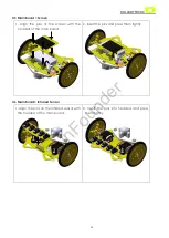
Страница 16: ...el 7 Put two M2 5 nuts into the screws Screw a little and then let the screw sink a bit till the nuts are fixed in the hole of the universal wheel 8 Fasten the screws with fingers pressing the nuts Then the universal wheel is fixed 4 4 Main Board Battery 1 Align the battery with the pin headers in the triangle region as shows below 4 Paste and press it tightly Then connect the power cord S u n F o...
Страница 17: ... screen with the headers of the main board 2 Insert the pins and press them tightly 4 6 Main Board Infrared Sensor 1 Align the pins on the infrared sensor with the headers of the main board 2 Insert the pins into headers and press them tightly S u n F o u n d e r ...
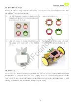
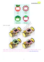
Страница 18: ...ouble sided tape on the upper and lower part of the OLED cover 4 There are four OLED covers in the kit Choose your favorite and stick it on 4 8 DIY Covers You can use the double sided tape to stick the fruit and flower covers on the OLED screen of the RollbotMicro It ll just feel like the cute bot is carrying an apple a watermelon hmm seems too heavy LOL or a blossoming flower The robot wearing th...
Страница 19: ...O 16 Pretty cute right What makes it more interesting is the DIY part You can design different clothes for the Rollbotmicro and welcome to share by post forums on our website www sunfounder com S u n F o u n d e r ...
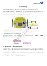
Страница 20: ... especially in the line following function Reset button To reset the master board Open the RollbotMicro folder downloaded and unzipped previously in Chapter 3 Software Operation You can see the following folders inside 5 1 Display the Sensor Signal Intensity on OLED This experiment is to display the collected sensor data on the OLED screen Here it is just applied for simple display Later in the li...
Страница 21: ...nd then click Tools Port select COM7 depending on your actual situation 3 Click Compile button to compile the code click upload to upload the code to the board or directly skip Compile Compile Upload S u n F o u n d e r ...
Страница 22: ... card under the sensor module of the robot Press the start button for more than 2 seconds to enter the debugging mode You will see that in the OLED screen there are five pillars simulating the signal intensity that the 5 sensors have collected Now put the first sensor on the left in the black stripe So the one showing 1 has the strongest signal As shown in figure below Start button S u n F o u n d...
Страница 23: ...he program since it s 0 by default 2 If the robot goes backward it means that both motors are wired inversely You need to change the variable value 0 of Speed_Dir into 1 to run the program normally 3 If the robot rotates clockwise always towards its right side it indicates the left motor is wired normally while the right one is done reversely You need to change the value 0 of Speed_Dir into 2 4 If...
Страница 24: ...icro 2 Take out the map and put it on a smooth surface like a table Turn on the robot and place it with the middle detector over the black line on the map Press the start button for more than 2 seconds The robot will test the reference value of the black line automatically Just wait patiently till it backs to the initial position after swaying a bit This process is to test the sampling value of th...
Страница 25: ...of line following After test the debugging process is as follows Set the PD to 0 and increase P slowly When the robot starts wiggling side to side increase the D value slowly to make the motion of the robot flat So the PD adjustment is done successfully 5 3 2 DIY Map On a blank paper you can draw a map you like according to instructions on the guide card Three patterns are provided and you can als...
Страница 26: ...to the initial position after swaying a bit This process is to test the sampling value of the black line Then the robot will move along the line You can try more possibilities such as using a white chalk to draw maps on a dark smooth surface like the floor set a gift at the end and then wait for the RollbotMicro to discover the mysteries The program for using chalk to draw the map is not provided ...
Страница 27: ...he robot by distinguishing the black and white surfaces Pin SCL SDA Simulates the intensity of black lines by the sensor and display it on the OLED screen thus enabling debugging with the OLED screen Pin D4 D7 D5 D6 Pin D4 and D5 for the control of the left motor s direction and speed when Pin D7 and D6 for the motor on the right Pin A6 Read its AD value so as to tell the battery power in a real t...
Страница 28: ...ROLLBOTMICRO 25 Other Controls These are the major control sections of the RollbotMicro You may check the circuit diagrams below by module names in different colors S u n F o u n d e r ...
Страница 29: ...ROLLBOTMICRO 26 6 3 USB Interface Module 6 4 LED Display Module S u n F o u n d e r ...
Страница 30: ...ROLLBOTMICRO 27 6 5 OLED Display Module For more information about the circuit diagram of the rest modules please refer to the WIKI page on our official website www sunfounder com S u n F o u n d e r ...
Страница 31: ...ge it to 0x00 and the LEDs will go out Output of data control void RollbotLED DataOut int val for int i 0 i 8 i if val 0x80 digitalWrite dataPin 1 else digitalWrite dataPin 0 val 1 digitalWrite clockPin HIGH delayMicroseconds 10 digitalWrite clockPin LOW digitalWrite latchPin LOW delayMicroseconds 10 digitalWrite latchPin HIGH 7 2 Sensor Signal Intensity on OLED Screen The OLED screen can display ...
Страница 32: ...f0 4 0x10 0x10 WriteCommand x 0x0f 0x00 0x01 Apart from the three basic functions you can use more for display on the OLED screen The current code is adequate for displaying sensor signal intensity easily For more information you can refer to the program RollbotOLED CPP in the library 7 3 Line Following The line following function is the most important function of the robot It distinguishes the bl...
Страница 33: ...eturn 4 else if data 0 threshold data 1 threshold data 2 threshold data 3 threshold data 4 threshold return 3 else if data 0 threshold data 1 threshold data 2 threshold data 3 threshold data 4 threshold return 2 else if data 0 threshold data 1 threshold data 2 threshold data 3 threshold data 4 threshold return 1 else if data 0 threshold data 1 threshold data 2 threshold data 3 threshold data 4 thr...
Страница 34: ...lines MotorSpeed P SignalValue D SignalValue LastError SignalValue is the gap between the position of RollbotMicro detected and that of the black line LastError is the error value accumulated till the last time SignalValue LastError means the rate of change of the relative position Motorpeed int P SignalValue D SignalValue LastError LastError 0 LastError SignalValue Speed_L BASE_SPEED Motorpeed Sp...
Страница 35: ...module is installed well Q2 The RollbotMicro runs on the map randomly and not following the black line A 1 Check whether you ve changed the value of Speed_Dir right before uploading the program Please refer to 5 2 Motor Testing 2 If the robot keeps spinning itself check whether the wire of one motor is loose Q3 I drew a map myself but the RollbotMicro just cannot follow the line on it A 1 Check wh...
Страница 36: ...ties permit and welcome to share with us Enjoy your time with the ROLLBOTMICRO Copyright Notice All contents including but not limited to texts images and code in this manual are owned by the SunFounder Company You should only use it for personal study investigation enjoyment or other non commercial or nonprofit purposes under the related regulations and copyrights laws without infringing the lega...