background image


Physik Instrumente (PI) GmbH & Co. KG, Auf der Roemerstrasse 1, 76228 Karlsruhe, Germany 
Phone +49 721 4846-0, Fax +49 721 4846-1019, Email [email protected], www.pi.ws 


MS207E 

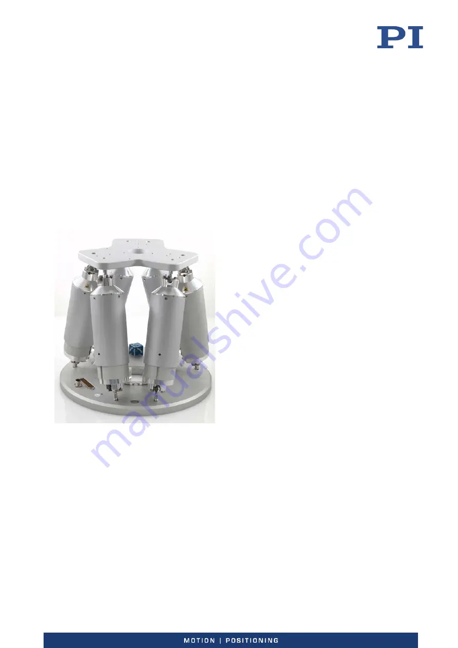
H-820 Hexapod Microrobot 

User Manual 

Version: 2.3.0 


Date: 04.12.2019 


This document describes the following product: 


H-820.D2


Hexapod microrobot, basis model, 20 mm/s, 

20 kg load, Sub-D connector (m), cable set 3 m 

Summary of Contents for H-820

Page 1: ...Phone 49 721 4846 0 Fax 49 721 4846 1019 Email info pi ws www pi ws MS207E H 820 Hexapod Microrobot User Manual Version 2 3 0 Date 04 12 2019 This document describes the following product H 820 D2 He...

Page 2: ...ademark of iC Haus GmbH 2019 Physik Instrumente PI GmbH Co KG Karlsruhe Germany The text photographs and drawings in this manual are protected by copyright With regard thereto Physik Instrumente PI Gm...

Page 3: ...ntrollers 8 3 4 Product View 9 3 5 Scope of Delivery 9 3 6 Accessories 10 3 7 Technical Features 12 3 7 1 Struts 12 3 7 2 Reference Switch and Limit Switches 12 3 7 3 Control 12 3 7 4 Motion 13 3 7 5...

Page 4: ...ice 39 10 Technical Data 41 10 1 Specifications 41 10 1 1 Data Table 41 10 1 2 Maximum Ratings 42 10 1 3 Cable Set Specifications 43 10 2 Ambient Conditions and Classifications 44 10 3 Dimensions 44 1...

Page 5: ...ng of basic servo systems as well as motion control concepts and applicable safety procedures The latest versions of the user manuals are available for download p 3 on our website 1 2 Symbols and Typo...

Page 6: ...mstances Photographic illustrations may also differ and must not be seen as guaranteed properties 1 4 Other Applicable Documents The devices and software tools from PI mentioned in this documentation...

Page 7: ...ment p 39 Downloading manuals 1 Open the website www pi ws 2 Search the website for the product number e g P 882 or the product family e g PICMA bender 3 Click the corresponding product to open the pr...

Page 8: ......

Page 9: ...with a suitable controller available from PI p 8 which coordinates all motion of the hexapod 2 2 General Safety Instructions The H 820 is built according to state of the art technology and recognized...

Page 10: ...er relevant information provided by the manufacturer Do the work only if the user manual is complete Missing information due to an incomplete user manual can result in minor injury and damage to equip...

Page 11: ...The parallel kinematic design offers the following advantages Positioning operations on six independent axes three translational axes three rotational axes with short settling times High accuracy and...

Page 12: ...TCP IP RS 232 benchtop device incl control of two additional axes motion stop analog inputs C 887 53 6 axis controller for hexapods TCP IP RS 232 benchtop device incl control of two additional axes Et...

Page 13: ...l plug for data transmission cable 6 Base plate 3 5 Scope of Delivery Order number Components H 820 Hexapod according to your order p 7 Cable set consisting of K040B0241 Data transmission cable HD D s...

Page 14: ...r Description C 887 5A03 Hexapod cable set 3 m consisting of Description Length Item number Data transmission cable HD D sub 78 f m 1 1 3 m K040B0490 Power supply cable M12 m f 1 1 3 m K060B0262 C 887...

Page 15: ...em number Data transmission cable HD D sub 78 f m 1 1 10 m K040B0296 Power supply cable M12 m f 1 1 10 m K060B0224 C 887 5A20 Hexapod cable set 20 m consisting of Designation Length Item number Data t...

Page 16: ...Limit Switches The reference switch of a strut functions independently of the angular positions of the strut ends and the lengths of the other struts When a limit switch is activated the power source...

Page 17: ...2 Coordinate system and rotations to the rotational coordinates U V and W The coordinate system is depicted above the platform for better clarity Translation Translations are described in the spatiall...

Page 18: ...ns INFORMATION For a clearer view the figures have been adapted as follows Round platform replaced by T shaped platform Coordinate system shown shifted Center of rotation in the top left corner of the...

Page 19: ...position 10 The rotation takes place around rotational axis V which was tilted during the previous rotation The rotation around the V axis tilts the rotational axes U and W Figure 4 Rotation around t...

Page 20: ...3 7 5 ID Chip The hexapod has an ID chip that contains data on the type of hexapod its serial number and the date of manufacture The data is loaded from the ID chip when the controller is switched on...

Page 21: ...in case the product needs to be transported later Unpacking the hexapod 1 Open the outer box 2 Remove the foam cushion 3 Open the inner box 4 Remove the corrugated cardboard insert and the foam cushi...

Page 22: ......

Page 23: ...he load of the hexapod with a simulation program p 20 The limit values determined with the simulation program are only valid when the controller has the servo mode switched on for the axes of the moti...

Page 24: ...apod Simulation Tool installed For further information see the A000T0068 technical note Determining the workspace and the permissible load of the hexapod Follow the instructions in the A000T0068 techn...

Page 25: ...is included in the scope of delivery of the cable set The snap on ferrite is intended for permanent attachment to the hexapod side cable of the power supply When attaching the snap on ferrite make su...

Page 26: ...two halves of the snap on ferrite around the cable until the lock engages 5 4 Grounding the Hexapod The hexapod is not grounded via the power supply cable If a functional grounding is required for pot...

Page 27: ...late Requirements You have read and understood the general notes on installation p 19 Tools and accessories Hex key 5 0 and three of the supplied screws p 9 Mounting the hexapod 1 Provide three M6 thr...

Page 28: ...ng installation Make sure that no collisions between the hexapod the load to be moved and the surroundings are possible in the workspace of the hexapod NOTICE Excessively long screws The hexapod can b...

Page 29: ...ws Fixing the load 1 Align the load so that at least three mounting holes in the motion platform can be used to fix the load The arrangement of the mounting holes in the motion platform of the hexapod...

Page 30: ...V Out 7 A connection on the controller is not available for the hexapod because this connection is required for the power supply of the hexapod side line driver box A C 887 5PS power supply for the h...

Page 31: ...set without line driver boxes Panel plug connector male Socket connector female Controller Refer to Suitable Controllers p 8 Hexapod H 820 D2 A Power adapter from the scope of delivery of the controll...

Page 32: ...xapod H 820 D2 A Controller side line driver box B Hexapod side line driver box C Power adapter 24 V DC output D Power adapter from the scope of delivery of the controller 24 V DC output 1 Data transm...

Page 33: ...ion of the controller The configuration data used by the controller e g geometrical data and servo control parameters must be adapted to the hexapod If incorrect configuration data is used the hexapod...

Page 34: ...rting Up the Hexapod System Requirements You have read and understood the general notes on startup p 29 You have correctly installed the hexapod i e you have mounted the hexapod onto a surface fixed t...

Page 35: ...exapod the following maintenance measures are required 7 1 Performing a Maintenance Run Frequent motion over a limited travel range can cause the lubricant to be distributed unevenly on the drive scre...

Page 36: ...e the data transmission cable and the power supply cable from the controller and the hexapod d Loosen the three M6x30 screws used to fix the hexapod on the underlying surface e Remove the three M6x30...

Page 37: ...8 Close the inner box 9 Put a 740 x 740 x 130 mm foam cushion onto the inner box see figure 10 Put the cover onto the outer box see figure 11 Secure the outer box on the pallet with two parallel stra...

Page 38: ...7 Maintenance 34 Version 2 3 0 MS207E H 820 Hexapod Microrobot Step 6 Right Appropriate orientation of the foam cover view from above Step 7 Step 9 Step 10...

Page 39: ...ains the controller 7 3 Cleaning the Hexapod Requirements You have removed the cables for data transmission and the power supply from the hexapod Cleaning the hexapod If necessary clean the surfaces o...

Page 40: ......

Page 41: ...joint Dirty encoder Carry out a strut test see user manual for the controller The strut test should be carried out in the reference position unless the malfunction occurs with maximum or minimum displ...

Page 42: ...ng elements in the PC software Note A new reference move is not necessary The hexapod does not move Incorrect or missing configuration data Send the CST command The response shows the hexapod to which...

Page 43: ...formation Product and serial numbers of all products in the system Firmware version of the controller if applicable Version of the driver or the software if applicable Operating system on the PC if ap...

Page 44: ......

Page 45: ...Y Z X Y Z Travel range X Y 50 mm Travel range Z 25 mm Travel range X Y 15 Travel range Z 30 Actuator drive Torque motor brushless BLDC Actuator design resolution 0 2 m typ Minimum incremental motion...

Page 46: ...100 N max Miscellaneous H 820 D2 Unit Tole rance Operating temperature range 0 to 50 C Material Aluminum Mass 15 kg 5 Cable length 3 m 10 mm Recommended controller C 887 5x Technical data specified at...

Page 47: ...l Unit Cable length L 1 2 3 5 7 5 10 20 50 1 2 3 5 7 5 10 20 Vacuum side 2 Air side 3 m Maximum velocity 3 m s Maximum acceleration 5 m s 2 Maximum number of bending cycles 1 million Operating tempera...

Page 48: ...ree of protection according to IEC 60529 IP20 Area of application For indoor use only Maximum altitude 2000 m 10 3 Dimensions The figure shows the hexapod in the reference position Dimensions in mm No...

Page 49: ...nection Data transmission between hexapod and controller Panel plug HD Sub D 78 m Function All signals TTL Pin Assignment Pin Pin Signal Pin Pin Signal 1 CH1 Sign IN 40 CH1 MAGN IN 21 CH1 Ref OUT 60 C...

Page 50: ...ef OUT 69 CH4 LimP OUT 11 nc 50 CH4 LimN OUT 31 CH4 A OUT 70 CH4 B OUT 12 CH4 A OUT 51 CH4 B OUT 32 GND 71 GND 13 CH5 Sign IN 52 CH5 MAGN IN 33 CH5 Ref OUT 72 CH5 LimP OUT 14 nc 53 CH5 LimN OUT 34 CH5...

Page 51: ...rnational national and local rules and regulations In order to fulfil its responsibility as the product manufacturer Physik Instrumente PI GmbH Co KG undertakes environmentally correct disposal of all...

Page 52: ......

Page 53: ...of rotation after a reference move is located at the origin of the coordinate system 0 0 0 see the dimensional drawing of the hexapod p 44 The center of rotation always moves together with the platfo...

Page 54: ...ot The Z axis is perpendicular to the base plate of the hexapod The following example figures of the H 810 hexapod show that the coordinate system does not move along with motion of the platform Figur...

Page 55: ...12 Glossary H 820 Hexapod Microrobot MS207E Version 2 3 0 51 Figure 14 H 810 hexapod the platform of which has been moved in X 1 Cable exit...

Page 56: ......

Page 57: ...he translational axes before delivery The performance test sheet is included in the scope of delivery The following figure shows the test setup used Figure 15 Test setup for measuring the X or Y axis...

Page 58: ......

Page 59: ...ation of Conformity For the H 820 an EU Declaration of Conformity has been issued in accordance with the following European directives EMC Directive RoHS Directive The applied standards certifying the...

Reviews: